CHASSIS
3-25
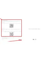
3. Check:
• Chain drive oil level
Wipe the dipstick clean, insert it into the oil fill-
er hole (without screw it in), and then remove
it to check the oil level.
The chain drive oil level should be between
the minimum level mark “a” and maximum
level mark “b”.
Below the minimum level mark
→
Add the
recommended chain drive oil to the proper
level.
4. Install:
• Chain drive oil filler cap
• Transmission chain drive case cover
EAS21490
CHANGING THE CHAIN DRIVE OIL
1. Stand the vehicle on a level surface.
TIP
• Place the vehicle on the centerstand.
• Make sure that the vehicle is upright.
2. Place a container under the chain drive.
3. Remove:
• Chain drive oil drain bolt “1”
(along with the gasket)
• Chain drive oil filler cap “2”
4. Drain:
• Chain drive oil
(completely from the chain drive case)
5. Check:
• Drain bolt gasket
Damage
→
Replace.
6. Install:
• Chain drive oil drain bolt
(along with the gasket)
7. Fill:
• Chain drive oil
(with the specified amount of the recom-
mended chain drive oil)
8. Check:
• Chain drive oil level
Refer to “CHECKING THE CHAIN DRIVE
OIL LEVEL” on page 3-24.
9. Install:
• Chain drive oil filler cap
EAS21500
CHECKING AND ADJUSTING THE
STEERING HEAD
1. Stand the vehicle on a level surface.
WARNING
EWA13120
Securely support the vehicle so that there is
no danger of it falling over.
TIP
Place the vehicle on a suitable stand so that the
front wheel is elevated.
Type
SAE 80 API GL-4 Hypoid gear
oil
T
R
.
.
Transmission chain drive case
cover screw
7 Nm (0.7 m·kg, 5.1 ft·lb)
b
a
T
R
.
.
Chain drive oil drain bolt
20 Nm (2.0 m·kg, 14 ft·lb)
Type
SAE 80 API GL-4 Hypoid gear
oil
Quantity
0.70 L (0.74 US qt) (0.62 Imp.qt)
2
1
Summary of Contents for 2009 XP500Y TMAX
Page 1: ...2009 SERVICE MANUAL XP500Y LIT 11616 22 08 4B5 28197 10 ...
Page 6: ......
Page 8: ......
Page 26: ...SPECIAL TOOLS 1 17 ...
Page 47: ...TIGHTENING TORQUES 2 20 Cylinder head tightening sequence ...
Page 56: ...LUBRICATION SYSTEM DIAGRAMS 2 29 1 2 3 4 4 ...
Page 57: ...LUBRICATION SYSTEM DIAGRAMS 2 30 1 Secondary shaft 2 Drive axle 3 Clutch 4 Crankshaft ...
Page 60: ...COOLING SYSTEM DIAGRAMS 2 33 1 2 3 4 5 6 7 8 9 10 11 12 ...
Page 64: ...CABLE ROUTING 2 37 A B A C D E F G H I J K L 1 2 1 2 3 3 4 5 6 6 7 A A A A A A A A ...
Page 78: ...CABLE ROUTING 2 51 ...
Page 81: ......
Page 115: ......
Page 172: ...FRONT FORK 4 57 2 3 ...
Page 186: ...SWINGARM AND TRANSMISSION CHAIN DRIVE 4 71 ...
Page 270: ...TRANSMISSION 5 81 ...
Page 294: ...THROTTLE BODY 7 9 ...
Page 297: ......
Page 309: ...CHARGING SYSTEM 8 12 2 AC magneto 3 Rectifier regulator 14 Battery 15 Main fuse ...
Page 311: ...CHARGING SYSTEM 8 14 ...
Page 321: ...SIGNALING SYSTEM 8 24 ...
Page 325: ...COOLING SYSTEM 8 28 ...
Page 353: ...FUEL PUMP SYSTEM 8 56 ...
Page 356: ...ELECTRICAL COMPONENTS 8 59 2 1 3 4 5 6 10 8 9 11 7 ...
Page 376: ...ELECTRICAL COMPONENTS 8 79 ...
Page 383: ......
Page 384: ...YAMAHA MOTOR CO LTD 2500 SHINGAI IWATA SHIZUOKA JAPAN ...