background image

– 7 –

SPEC

CABLE ROUTING

å

ç

´

ƒ

©

˙

ˆ

˚

¬

µ

1

2

3

4

5

6

7

8

9

0

©

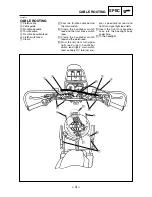
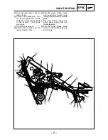
Pass the wireharness to the far-
thest left side.

˙

Clamp the wireharness, CDI
unit lead, magneto lead, throttle
cable, and starter (choke) cable
on the center of the engine
mount stay.

ˆ

Clamp the wireharness.

Clamp the handlebar switch
lead and clutch cable.

˚

Pass the starter (choke) cable
and handlebar switch lead
through the outside of the cable
guide.

¬

Pass the throttle cable and
clutch cable (under side) into
the cable guide .

µ

Pass the starter (choke) cable
in front of the throttle cable and
clutch cable.

Summary of Contents for 2003 AG200F

Page 1: ...AG200F SUPPLEMENTARY SERVICE MANUAL 2003 3GX AE2 ...

Page 2: ...he written permission of Yamaha Motor Co Ltd is expressly prohibited EAS00000 FOREWORD This Supplementary Service Manual has been prepared to introduce new service and data for the AG200F 2003 For complete service information procedures it is necessary to use this Supplementary Service Manual together with the following manual AG200F 97 SERVICE MANUAL 3GX AE1 ...

Page 3: ...s models Modifications and sig nificant changes in specifications or procedures will be forwarded to all authorized Yamaha dealers and will appear in future editions of this manual where applicable NOTE Designs and specifications are subject to change without notice EAS00004 IMPORTANT MANUAL INFORMATION Particularly important information is distinguished in this manual by the following Q The Safet...

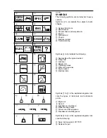
Page 4: ...luid q Lubricant w Special tool e Tightening torque r Wear limit clearance t Engine speed y Electrical data Symbols u to s in the exploded diagrams indi cate the types of lubricants and lubrication points u Engine oil i Gear oil o Molybdenum disulfide oil p Wheel bearing grease a Lithium soap based grease s Molybdenum disulfide grease Symbols d to f in the exploded diagrams indi cate the following...

Page 5: ...ATIONS 2 CHASSIS 2 ELECTRICAL 2 TIGHTENING TORQUES 3 ENGINE 3 CABLE ROUTING 4 PERIODIC CHECKS AND ADJUSTMENTS 8 INTRODUCTION 8 PERIODIC MAINTENANCE AND LUBRICATION INTERVALS 8 ELECTRICAL 10 IGNITION SYSTEM 10 CIRCUIT DIAGRAM 10 TROUBLESHOOTING 11 AG200F 2002 WIRING DIAGRAM ...

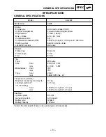
Page 6: ...Chassis Frame type Diamond Caster angle 27 42 Trail 87 mm Tire Type With tube Size front 80 100 21 51M rear 4 10 18 59M Manufacturer front IRC rear IRC Type front VE 32 rear FARM SPECIAL Z2 Tire pressure cold tire Maximum load except motorcycle 112 kg Loading condition A 0 112 kg off road riding front 120 kPa 1 2 kgf cm2 17 4 psi rear 150 kPa 1 5 kgf cm2 21 8 psi Electrical Ignition system DC CDI ...

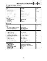
Page 7: ...facturer 3GX YAMAHA Pickup coil resistance color 656 984 Ω at 20 C Red White Ignition coil Model manufacturer 2JN YAMAHA Minimum spark gap 6 mm Primary winding resistance 0 24 0 36 Ω at 20 C Secondary winding resistance 5 68 8 52 kΩ at 20 C Charging system Type CDI magneto Model manufacturer F5MP YAMAHA Standard output 14 V 175W 5 000 r min Stator coil resistance color 0 56 0 84 Ω at 20 C White Wh...

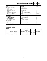
Page 8: ...tem Type Constant mesh type Starter motor Model manufacturer 4JG YAMAHA Output 0 4 kW Armature coil resistance 0 0126 0 0154 Ω at 20 C Brush overall length 10 mm 3 5 mm Brash spring pressure 5 52 8 28 N 563 844g Starter relay Model manufacturer MS5F 431 JIDECO Amperage rating 180 A Coil winding resistance 4 18 4 62 Ω at 20 C Flasher relay Type Full transistor type Model manufacturer FE218BH DENSO ...

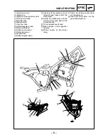
Page 9: ...r switch lead and the front brake switch lead ç Clamp the handlebar switch lead and the clutch lead From the left front turn signal light lead right handlebar switch lead right main switch lead auxiliary DC terminal cou pler speedometer lead and front turn signal light lead left Insert the front fork breather hose into the headlight body under hole ƒ To the headlight EAS00035 CABLE ROUTING å ç ƒ 1...

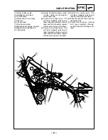
Page 10: ...d 0 Battery positive lead q Starter relay lead w Wireharness e Battery negative lead å Tighten with the ignition coil and the earth lead bypass from the wireharness Clamp the wireharness and the starting motor lead behind the air cleaner duct ç To the regulator earth lead Black coupler to the regulator coupler White coupler to the starter relay ƒ Clamp the battery positive lead and wireharness Ins...

Page 11: ...ch lead left Clamp the wireharness CDI unit lead magneto pickup coil lead magneto charge neutral lead and throttle cable coupler with front and rear by the band ç Clamp the wireharness CDI unit lead magneto pickup coil lead magneto charge neutral lead and throttle cable coupler with front and rear by the band Clamp the wireharness CDI unit lead magneto pickup coil lead and starting motor lead Alig...

Page 12: ...ter choke cable on the center of the engine mount stay ˆ Clamp the wireharness Clamp the handlebar switch lead and clutch cable Pass the starter choke cable and handlebar switch lead through the outside of the cable guide Pass the throttle cable and clutch cable under side into the cable guide µ Pass the starter choke cable in front of the throttle cable and clutch cable ...

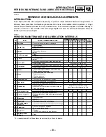
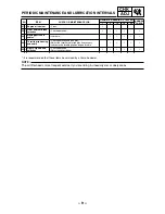
Page 13: ...er free play Replace brake shoes Whenever worn to the limit 7 Rear brake Check operation and adjust brake pedal free play Replace brake shoes Whenever worn to the limit 8 Wheels Check runout spoke tightness and for damage Tighten spokes if necessary 9 Tires Check tread depth and for damage Replace if necessary Check air pressure Correct if necessary 10 Wheel bearings Check bearing for looseness or...

Page 14: ... Engine oil strainer Clean 22 Front and rear brake switches Check operation 23 Moving parts and cables Lubricate 24 Throttle grip housing and cable Check operation and free play Adjust the throttle cable free play if necessary Lubricate the throttle grip housing and cable 25 Lights signals and switches Check operation Adjust headlight beam NO ITEM CHECK OR MAINTENANCE JOB ODOMETER READING 1 000 km...

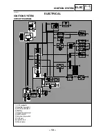
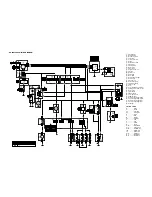
Page 15: ... P P B P Br P Br L B Dg B Dg B Ch B Ch B B Y Br Sb Br L W B B Br Y Br Br W Br W Y Y G Ch Dg G Y L B Sb B L Y R L Y Br R W L W R W R W L W R R R B B W B W B Br Br L Y L Y B R W R W R W L W B B B B Y B Y f d s g a 8 9 6 7 p t o i 5 4 3 2 1 w r e 0 q c z v x k h l j b EAS00734 ELECTRICAL IGNITION SYSTEM CIRCUIT DIAGRAM 10 ELEC IGNITION SYSTEM 1 CDI magneto 3 Rectifier regulator 5 Positive wire lead 6...

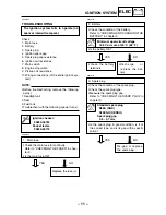
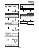
Page 16: ...rk plug 9Check the condition of the spark plug 9Check the spark plug type 9Measure the spark plug gap Refer to CHECKING THE SPARK PLUG in chapter 3 9Is the spark plug in good condition is it of the correct type and is its gap within specifi cation YES NO Re gap or replace the spark plug Standard spark plug D8EA NGK X24ES U DENSO Spark plug gap 0 6 0 7 mm EAS00738 1 Main fuse 9Check the main fuse f...

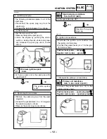
Page 17: ...744 5 Spark plug cap resistance 9Remove the spark plug cap from the spark plug lead 9Connect the pocket tester Ω x 1k range to the spark plug cap as shown 9Measure the spark plug cap resistance Primary coil resistance 0 24 0 36 Ω at 20 C 68 F EAS00743 4 Ignition spark gap The following procedure applies to all of the spark plug 9Disconnect the spark plug cap from the spark plug 9Connect the igniti...

Page 18: ... wiring properly con nected and without defects YES NO Properly connect or repair the ignition system s wiring Replace the CDI unit 9Measure the pickup coil resistance 9Is the pickup coil OK Pickup coil resistance 656 984 Ω at 20 C 68 F between red and white YES NO Replace the pick up coil 9Measure the secondary coil resistance 9Is the ignition coil OK YES NO Replace the ignition coil Secondary co...

Page 19: ...YAMAHA MOTOR CO LTD 2500 SHINGAI IWATA SHIZUOKA JAPAN ...

Page 20: ...light COLOR CODE B Black Br Brown Ch Chocolate Dg Dark green G Green L Blue O Orange Sb Sky blue P Pink R Red Y Yellow W White B W Black White B Y Black Yellow Br W Brown White L W Blue White L Y Blue Yellow R W Red White W L White Blue W R White Red B B Or Or W R W L L Y Br W R W L B Y B B G B B B B B B Br W R W L L Y Or B R R W B B B W W W W W R W W W R W W R W L PU IGN PU GND STOP ON OFF ON OFF...

Reviews: