


2
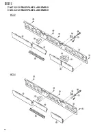
MC32/12
MC24/12
IMPORTANT NOTICE
This manual has been provided for the use of authorized Yamaha Retailers and their service personnel. It has been
assumed that basic service procedures inherent to the industry, and more specifically Yamaha Products, are already
known and understood by the users, and have therefore not been restated.
WARNING:
Failure to follow appropriate service and safety procedures when servicing this product may
result in personal injury, destruction of expensive components and failure of the product to
perform as specified. For these reasons, we advise all Yamaha product owners that all service
required should be performed by an authorized Yamaha Retailer or the appointed service
representative.
IMPORTANT:
This presentation or sale of this manual to any individual or firm does not constitute authoriza-
tion, certification, recognition of any applicable technical capabilities, or establish a principal-
agent relationship of any form.
The data provided is believed to be accurate and applicable to the unit(s) indicated on the cover. The research
engineering, and service departments of Yamaha are continually striving to improve Yamaha products. Modifications
are, therefor, inevitable and changes in specification are subject to change without notice or obligation to retrofit.
Should any discrepancy appear to exist, please contact the distributor's Service Division.
WARNING:
Static discharges can destroy expensive components. Discharge any static electricity your body
may have accumulated by grounding yourself to the ground bus in the unit (heavy gauge black
wires connect to this bus).
IMPORTANT:
Turn the unit OFF during disassembly and parts replacement. Recheck all work before you
apply power to the unit.
WARNING: CHEMICAL CONTENT NOTICE!
The solder used in the production of this product contains LEAD. In addition, other electrical / electronic and / or
plastic (where applicable) components may also contain traces of chemicals found by the California Health and
Welfare Agency (and possibly other entities) to cause cancer and / or birth defects or other reproductive harm.
DO NOT PLACE SOLDER, ELECTRICAL / ELECTRONIC OR PLASTIC COMPONENTS IN YOUR MOUTH FOR
ANY REASON WHAT SO EVER!
Avoid prolonged, unprotected contact between solder and your skin! When soldering, do not inhale solder fumes or
expose eyes to solder / flux vapor!
If you come in contact with solder or components located inside the enclosure of this product, wash your hands before
handling food.
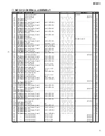
WARNING
Components having special characteristics are marked
and must be replaced with parts having specification equal to those originally
installed.
Summary of Contents for MC32/12
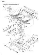
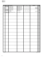
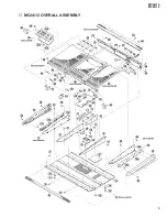
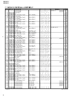
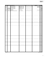
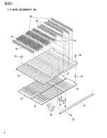
Page 4: ...2 MC32 12 MC24 12 MC32 12 OVERALL ASSEMBLY...
Page 7: ...5 MC32 12 MC24 12 MC24 12 OVERALL ASSEMBLY...
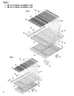
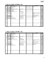
Page 10: ...8 MC32 12 MC24 12 PANEL ASSEMBLY IN1...
Page 12: ...10 MC32 12 MC24 12 MC32 12 PANEL ASSEMBLY IN2 MC24 12 PANEL ASSEMBLY IN2...
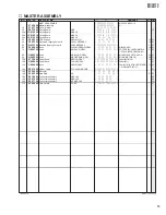
Page 14: ...12 MC32 12 MC24 12 MASTER ASSEMBLY...
Page 16: ...14 MC32 12 MC24 12 MC32 12 REAR PANEL ASSEMBLY MC24 12 REAR PANEL ASSEMBLY...