background image

GB-7

GB

ARRANGING THE EXHAUST

When the exhaust point needs to be set up away from the 

pump, arrange the exhaust.

Use a pipe/hose of the same diameter as the exhaust port.

 CAUTION

Blocking the exhaust or using more than 

5 meters length of exhaust pipe/hose may 

lead to a decreased pump performance.

 CAUTION

When operating the product, it may 

generate loud operating noise, depending 

upon the circumstances.

 WARNING

Protect humans, animals and surrounding 

facilities against the exhaust port.

CONNECTING AIR PIPING

Connect a filter regulator between the compressor and the 

pump, and use a lubricator if required. Use a flexible air 

hose with a diameter equal to the inlet air valve and the air 

consumption. Keep the air line as short as possible for best 

performance.

 WARNING

Make sure the air valve is placed in such 

a way, that it can be reached in case of 

emergency.

 WARNING

Always use Class 1 turbine oil (ISO VG32) 

only for lubrication in non-explosive 

environments.

CONNECTING FLUID PIPING

When connecting a pipe or hose to the manifold, never tighten 

it too strongly. Otherwise, the manifold may be damaged.

Connect to manifold as follows:
1.  Apply sealing tape to a thread of a joint or the connector, 

which need to be connected to the manifold.

2.  Screw into the manifold correctly and tighten fully by hand.

3.  Then, screw the thread further for two rounds with a tool. 

In case of a leakage, tighten it little by little additionally.

When using a rigid pipe, connect flexible connections on both 

the inlet and the discharge port.

Pipe and hose diameters should be the same as or bigger 

than the pump port size. Long suction and discharge lines 

can decrease pump performance.

Refer to the diagram under “INSTALLATION OF THE PUMP” 

for an installation example.
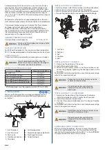
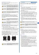
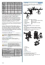
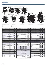
 CAUTION

For NDP-50FAN, the inlet port is located on 

top of the pump. It discharges liquid from 

the bottom side port.

OUTLET

INLET

OUTLET

INLET

OUTLET

INLET

NDP-50FAN

STANDARD PUMPS

6.  OPERATION

Before connecting any pipes or hoses to the pump, make 

sure that the system has been bled of all compressed air.

START-UP
Pump

1.  Check all bolt torque values on the outside of the pump 

(refer to DOC-1 in the APPENDIX).

2.  Make sure that the supply and pump air valve, regulator 

and the drain valve on the discharge side are closed. 

Also, make sure that the inlet flow valve on the suction 

side is open.

3.  Start the air compressor.

4.  Open the supply air valve and adjust the supply air 

pressure with a regulator to within the permissible range 

(Refer to OPERATING PRESSURE RANGE on page GB-6)

5.  Open the flow valve on the discharge side.

6.  Press the RESET button (excluding G15P, G15V and G25) 

and then slowly open the air valve of the pump.

7.  Verify that fluid is flowing inside the piping and is being 

pumped to the discharge side, and then fully open the 

air valve.

8.  Again adjust the supply air pressure with a regulator to 

within the permissible range in order to adjust the flow 

rate. (Refer to OPERATING PRESSURE RANGE on page 

GB-6)

 WARNING

Do not open the air valve suddenly.

 WARNING

Never block a leakage with any body part. 

Injected materials can cause severe injury 

or death. 

 CAUTION

Slow pump cycles result in less wear and tear.

Dampener

1.  Start the air compressor and operate the pump.

2.  Set the supply air pressure to the reference level of 

“pump discharge pressure x 1.1” by using the regulator 

connected to the dampener and make a fine adjustment 

in the range of ±0.05 MPa while checking the pulsation 

as required.

SHUT DOWN
Pump and Dampener

1.  Close the supply air valve and the air valve of the pump to 

shut off the supply air.

2.  Close the flow valve on the discharge side, start slowly 

opening the drain valve, and release the pressure fluid.

3.  Open the air valve of the pump, start running the pump, 

and discharge the remaining air.

4.  After making sure that the pump has been shut down and 

the pressure has been released, fully open the regulator, 

and close the air valve and drain valve of the pump.

5.  Flush the entire system with a proper cleaning liquid, 

especially if the pumped material is subject to expansion 

or dry-out when not in use.

6.  Disconnect the air line from the pump if it is not going to be 

active for a longer period.

7.  When using a dampener: if the pump is not running, shut 

off the air supply to the dampener. This to prevent possible 

damage of the dampener’s diaphragm.

Summary of Contents for DP Series

Page 1: ...glish Deutsch Espa ol Fran ais Italiano Nederlands Polski GB DE ES FR IT NL PL RU Doc No NDP 570U 00 YAMADA CORPORATION Quick Guide DP NDP G AD Series Copyright C Yamada Corporation All Rights Reserve...

Page 2: ...into the out chamber on the other side When the centre rod is moved full stroke to the right side the air switch valve is switched compressed air is distributed to the left side air chamber and the c...

Page 3: ...connection in flammable environment or when handling flammable liquid Perform a daily inspection at the beginning of each day Immediately stop operation if any defect is found Liquid may spurt out of...

Page 4: ...noise depending on the circumstances such as fluids to be transferred supplied air pressure and fluid discharge pressure When necessary for example if any law or regulation is applicable for the use o...

Page 5: ...tall the piping and exhaust port of this pump away from areas where humans or animals pass through If a dangerous fluid such as a n poison acid alkali chemical etc comes into contact with your skin or...

Page 6: ...played on the pump and surrounding area and all other safeguards are carried out 1 Inlet fluid port 6 Air filter regulator 2 Inlet flow valve 7 Pulsation dampener optional 3 Drain valve 8 Discharge fl...

Page 7: ...p 1 Check all bolt torque values on the outside of the pump refer to DOC 1 in the APPENDIX 2 Make sure that the supply and pump air valve regulator and the drain valve on the discharge side are closed...

Page 8: ...instructed that special tools must be used be sure to use the specified tools Otherwise the product may be damaged For details on maintenance refer to the maintenance manual or consult the Yamada Euro...

Page 9: ...GB 9 GB...

Page 10: ...H S 10 13 T TU 12 13 NDP 23BA BS TU 20 20 13 TU 25 35 20 Model a b c NDP P 25BA BF BS C E N V 10 10 H S 10 20 T TU G 35 20 NDP P 25BP C E N V 10 10 H S 10 20 T TU 12 20 NDP P 25BV C E N V 10 10 H S T...

Page 11: ...h IIC T6 T5 T4 Gb Ex h IIIC T95 C Db 1 Specific marking of explosion protection 2 Equipment of group II 3 Equipment of category 2 4 Explosive atmospheres caused by gases vapours or mists 5 Equipment o...

Page 12: ...nstange um den gesamten Hub nach rechts bewegt wird das Luftschaltventil umgeschaltet die linke Luftkammer mit Druckluft beaufschlagt und die Kolbenstange nach links bewegt Die Fl ssigkeit in der link...

Page 13: ...iten eine Schutzleiterverbindung herstellen Vor der Inbetriebnahme eine t gliche Kontrolle durchf hren Bei Auftritt eines Defekts den Betrieb umgehend einstellen Aufgrund eines mechanischen Versagens...

Page 14: ...je nach den Einsatzbedingungen gef rderte Fl ssigkeit zugef hrter Luftdruck Fl ssigkeitsf rderdruck usw ein lautes Betriebsger usch erzeugen Gegebenenfalls wenn z B diesbez glich Gesetze oder Vorschri...

Page 15: ...he s ure oder laugenhaltige entz ndliche oder giftige Fl ssigkeiten bzw Gasblasen die von solchen Fl ssigkeiten erzeugt werden k nnen bei versehentlichem Einatmen oder Verschlucken bei Augenkontakt od...

Page 16: ...ich f r alle Werkstoffe geeignet OBERFL CHENTEMPERATUR Bei ATEX zertifizierten Ger ten wurde die maximale Oberfl chentemperatur T95 C ohne Vorhandensein einer Staubschicht ermittelt BETRIEBSLUFT Die P...

Page 17: ...SLEITUNGSVERBINDUNGEN Rohr oder Schlauchverbindungen am Verteiler nicht berziehen Andernfalls kann der Verteiler besch digt werden Die Verbindung zum Verteiler wie folgt durchf hren 1 Das Gewinde des...

Page 18: ...Niederlassung auf Seite DE 18 kontaktieren WARNUNG Es k nnen R ckst nde aus der Pumpe austreten Pers nliche Schutzausr stung verwenden WARNUNG Nur Originalersatzteile von Yamada verwenden Andernfalls...

Page 19: ...Co Ltd Festlandchina Building No 12 No 1500 Zuchongzhi Road Pudong New District Shanghai 201203 P R China Telefon 86 0 21 3895 3699 Fax 86 0 21 5080 9755 E Mail admin yamadacorp com cn Website https w...

Page 20: ...S 10 13 T TU 12 13 NDP 23BA BS TU 20 20 13 TU 25 35 20 Modell a b c NDP P 25BA BF BS C E N V 10 10 H S 10 20 T TU G 35 20 NDP P 25BP C E N V 10 10 H S 10 20 T TU 12 20 NDP P 25BV C E N V 10 10 H S T T...

Page 21: ...IIIC T95 C Db 1 Explosionsschutzzeichen 2 Ger te der Gruppe II 3 Ger te der Kategorie 2 4 Explosionsgef hrdete Gas Dampf und Nebelatmosph ren 5 Ger te der Kategorie 2 6 Explosionsgef hrdete Staubatmos...

Page 22: ...central se acciona completamente hacia el lado derecho se activa la v lvula de desv o de aire el aire comprimido se distribuye por la c mara de aire del lado izquierdo y la varilla central se mueve ha...

Page 23: ...en los productos Indica lo siguiente ADVERTENCIA Lea atentamente todas las instrucciones antes del funcionamiento Cumpla con las especificaciones del producto Utilice aire comprimido o nitr geno para...

Page 24: ...o Consulte un gr fico de resistencia qu mica para asegurarse de que los materiales del producto sean adecuados para el fluido que se va a bombear Nunca utilice un producto qu mico que no sea adecuado...

Page 25: ...aje Los productos no se deben alimentar con gases inflamables Tenga en cuenta los peligros asociados con la aplicaci n espec fica y el entorno de aplicaci n Cumpla con todas las leyes normativas y c d...

Page 26: ...mpuesto de pl stico la presi n de aire m xima permitida puede estar limitada por la temperatura del fluido Las temperaturas de los materiales solo indican que los materiales pueden mantener una determ...

Page 27: ...manguera del mismo di metro que el orificio de escape PRECAUCI N Bloquear el escape o utilizar una tuber a manguera de escape de m s de 5 metros de longitud puede provocar una reducci n del rendimien...

Page 28: ...periodo prolongado 7 Si utiliza un amortiguador si la bomba no est funcionando cierre el suministro de aire hacia el amortiguador As evitar posibles da os en la membrana del amortiguador ADVERTENCIA...

Page 29: ...r nico intl yamadacorp co jp Web www yamadacorp co jp Yamada America Inc Estados Unidos Canad Am rica del Sur 955 E Algonquin Rd IL 60005 Arlington Heights Estados Unidos Tel fono 1 847 631 9200 1 800...

Page 30: ...0 H S 10 13 T TU 12 13 NDP 23BA BS TU 20 20 13 TU 25 35 20 Modelo a b c NDP P 25BA BF BS C E N V 10 10 H S 10 20 T TU G 35 20 NDP P 25BP C E N V 10 10 H S 10 20 T TU 12 20 NDP P 25BV C E N V 10 10 H S...

Page 31: ...IIC T6 T5 T4 Gb II 2 G 2 D Ex h IIC T6 T5 T4 Gb Ex h IIIC T95 C Db 1 Marcado espec fico de protecci n contra explosiones 2 Equipo de grupo II 3 Equipo de categor a 2 4 Atm sferas explosivas provocada...

Page 32: ...ns la chambre externe est refoul et simultan ment aspir dans la chambre externe de l autre c t Lorsque l arbre se trouve compl tement droite le clapet d inversion de l air comprim est activ l air comp...

Page 33: ...ors de la manipulation de liquide inflammable Effectuez une inspection au d but de chaque journ e Arr tez imm diatement le produit si un d faut est d tect Du liquide peut jaillir par le port d vacuati...

Page 34: ...tilisez des capteurs appropri s capables de signaler une d faillance ou d arr ter le fonctionnement du produit V rifiez galement que les mises en garde appropri es sont affich es sur le produit et les...

Page 35: ...es en vigueur N utilisez pas le produit si vous doutez qu il puisse tre utilis en toute s curit PR CAUTIONS PRENDRE Si vous utilisez le mod le certifi CSA consultez le revendeur chez lequel vous avez...

Page 36: ...central est en plastique il se peut que la pression d air maximale autoris e soit limit e par la temp rature du fluide Les temp ratures des mat riaux donnent seulement une indication sur leur robuste...

Page 37: ...n tuyau un flexible du m me diam tre que le port d vacuation PR CAUTIONS PRENDRE L obstruction de l vacuation ou l utilisation de plus de cinq m tres de tuyau flexible pour l vacuation peut entra ner...

Page 38: ...particulier si la mati re pomp e est sujette dilatation ou se dess che lorsqu elle n est pas utilis e 6 Enlevez la conduite d air de la pompe si vous ne l utilisez pas pendant longtemps 7 Si vous util...

Page 39: ...jp Yamada Corporation International Department Asie de l Est Asie du Sud Oc anie 1 1 3 Minami Magome Ota ku Tokyo 143 8504 Japon T l phone 81 0 3 3777 0241 Fax 81 0 3 3777 0584 E mail intl yamadacorp...

Page 40: ...0 10 H S 10 13 T TU 12 13 NDP 23BA BS TU 20 20 13 TU 25 35 20 Mod le a b c NDP P 25BA BF BS C E N V 10 10 H S 10 20 T TU G 35 20 NDP P 25BP C E N V 10 10 H S 10 20 T TU 12 20 NDP P 25BV C E N V 10 10...

Page 41: ...2 G 2 D Ex h IIC T6 T5 T4 Gb Ex h IIIC T95 C Db 1 Marquage sp cifique de la protection contre les explosions 2 quipement de groupe II 3 quipement de cat gorie 2 4 Atmosph res explosives en raison de...

Page 42: ...a compressa viene distribuita alla camera d aria sinistra e l asta centrale si sposta verso sinistra Il fluido all interno della camera di uscita sinistra viene spinto fuori e contemporaneamente il fl...

Page 43: ...liquido infiammabile Eseguire un controllo all inizio di ogni giornata Interrompere immediatamente l uso se si rilevano difetti Un guasto meccanico pu far schizzare fuori il liquido dallo scarico dell...

Page 44: ...Con il passare del tempo il serraggio di tutti i componenti del prodotto possono allentarsi Controllare e riserrare periodicamente tutti i bulloni alle rispettive tolleranze specificate consultare i...

Page 45: ...sempio l applicazione i fluidi di processo e l atmosfera L utilizzatore finale deve fare s che tutte le temperature siano accettabili PERICOLI PER LA SALUTE Verificare sempre tutte le leggi norme e re...

Page 46: ...i L applicazione e l uso del prodotto deve essere deciso in base alle caratteristiche del fluido pompato in combinazione con la temperatura la pressione e le caratteristiche o i requisiti fisici dell...

Page 47: ...della mandata della pompa o dello smorzatore PRUDENZA Se si blocca lo scarico o si usa un tubo rigido flessibile di scarico lungo pi di 5 metri le prestazioni della pompa possono calare PRUDENZA Quan...

Page 48: ...alimentazione se la pompa rester inutilizzata per un periodo di tempo prolungato 7 Quando si usa uno smorzatore se la pompa non in funzione interrompere l erogazione dell aria allo smorzatore Cos face...

Page 49: ...Fax 81 0 3 3777 0584 E mail intl yamadacorp co jp Sito web www yamadacorp co jp Yamada America Inc USA Canada Sud America 955 E Algonquin Rd IL 60005 Arlington Heights USA Telefono 1 847 631 9200 1 80...

Page 50: ...V 10 10 H S 10 13 T TU 12 13 NDP 23BA BS TU 20 20 13 TU 25 35 20 Modello a b c NDP P 25BA BF BS C E N V 10 10 H S 10 20 T TU G 35 20 NDP P 25BP C E N V 10 10 H S 10 20 T TU 12 20 NDP P 25BV C E N V 1...

Page 51: ...1 Marcatura specifica della protezione contro le esplosioni 2 Apparecchiatura del gruppo II 3 Apparecchiatura della categoria 2 4 Atmosfere esplosive causate da gas vapori o nebbie 5 Apparecchiatura...

Page 52: ...eleid en de centrale as beweegt naar links De vloeistof in de linker vloeistofkamer wordt naar buiten geperst terwijl er tegelijkertijd vloeistof in de rechter vloeistofkamer wordt gezogen Door herhal...

Page 53: ...als er een defect wordt aangetroffen Door mechanische defecten kan vloeistof uit de uitlaatpoort worden gestoten Neem beschermende maatregelen Laat voor demontage enige restdruk en achtergebleven vloe...

Page 54: ...ikte waarschuwingen aanwezig zijn op het product en in de directe omgeving ervan en dat alle andere veiligheidsmaatregelen in acht worden genomen In de loop der tijd kunnen de aanhaalmomenten van alle...

Page 55: ...verse factoren zoals de toepassing de procesvloeistoffen en de atmosfeer De eindgebruiker dient te verzekeren dat alle temperaturen acceptabel zijn GEZONDHEIDSGEVAREN Raadpleeg altijd alle toepasselij...

Page 56: ...ke eigenschappen of vereisten van de toepassing zelf OMGEVINGSTEMPERATUURBEREIK Behuizing van pompen en dempers 0 C tot 70 C WAARSCHUWING Gebruik altijd het temperatuurbereik dat geschikt is voor alle...

Page 57: ...smering in niet explosieve omgevingen DE VLOEISTOFLEIDINGEN AANSLUITEN Zet koppelingen voor het aansluiten van leidingen of slangen op het verdeelstuk niet te vast Anders kan het verdeelstuk beschadig...

Page 58: ...hiervoor de lijst op pagina NL 58 WAARSCHUWING Er kunnen resten uit de pomp worden gestoten Gebruik beschermingsmiddelen WAARSCHUWING Gebruik uitsluitend originele Yamada vervangingsonderdelen Anders...

Page 59: ...td vasteland van China Building No 12 No 1500 Zuchongzhi Road Pudong New District Shanghai 201203 P R China Telefoon 86 0 21 3895 3699 Fax 86 0 21 5080 9755 Mail admin yamadacorp com cn Web https www...

Page 60: ...10 10 H S 10 13 T TU 12 13 NDP 23BA BS TU 20 20 13 TU 25 35 20 Model a b c NDP P 25BA BF BS C E N V 10 10 H S 10 20 T TU G 35 20 NDP P 25BP C E N V 10 10 H S 10 20 T TU 12 20 NDP P 25BV C E N V 10 10...

Page 61: ...ieke markering voor explosiebescherming 2 Apparatuur van groep II 3 Apparatuur van categorie 2 4 Explosieve atmosferen veroorzaakt door gassen dampen of nevels 5 Apparatuur van categorie 2 6 Explosiev...

Page 62: ...ego jest prze czany spr one powietrze jest przekierowywane do lewej komory powietrznej i centralny wa przesuwa si w lewo P yn w lewej komorze wyj ciowej jest t oczony i w tej samej chwili p yn jest za...

Page 63: ...ego U ywa rodk w ochrony osobistej W przypadku pracy w atwopalnym rodowisku lub z atwopaln ciecz pod czy uziemienie Ka dego dnia wykonywa codzienn kontrol W przypadku stwierdzenia dowolnej usterki nat...

Page 64: ...a gor ce itp nale y przygotowa zabezpieczenia na przyk ad umie ci produkt w zag bieniu lub ochronnej obudowie oraz odpowiednie czujniki ostrzegaj ce o awarii lub zatrzymuj ce prac produktu Zawsze nale...

Page 65: ...przypadku jakichkolwiek w tpliwo ci dotycz cych bezpiecze stwa w zastosowaniu UWAGA W przypadku stosowania modeli z certyfikacj CSA nale y skonsultowa si ze sprzedawc danego produktu Temperatur powie...

Page 66: ...C W przypadku PPG zakres temperatur materia u wynosi od 0 C do 70 C W przypadku produkt w z kompozyt w tworzyw sztucznych maksymalne dopuszczalne ci nienie powietrza mo e by ograniczone temperatur p...

Page 67: ...jego lini Wymagana jest rura lub w o tej samej rednicy co z cze wylotu rozpr onego powietrza UWAGA Zablokowanie wylotu gazu lub zastosowanie rury lub w a o d ugo ci przekraczaj cej 5 metr w mo e zmnie...

Page 68: ...wyschn po zaprzestaniu u ytkowania 6 Od czy lini pneumatyczn od pompy je li nie b dzie u ywana przez d u szy czas 7 Je li jest u ywany t umik kiedy pompa nie pracuje od czy zasilanie pneumatyczne od...

Page 69: ...Department Azja Wschodnia Azja Po udniowa Oceania 1 1 3 Minami Magome Ota ku Tokyo 143 8504 Japonia Telefon 81 0 3 3777 0241 Faks 81 0 3 3777 0584 E mail intl yamadacorp co jp Strona internetowa www y...

Page 70: ...10 H S 10 13 T TU 12 13 NDP 23BA BS TU 20 20 13 TU 25 35 20 Model a b c NDP P 25BA BF BS C E N V 10 10 H S 10 20 T TU G 35 20 NDP P 25BP C E N V 10 10 H S 10 20 T TU 12 20 NDP P 25BV C E N V 10 10 H...

Page 71: ...T4 Gb Ex h IIIC T95 C Db 1 Szczeg lne oznaczenia ochrony przeciwwybuchowej 2 Wyposa enie grupy II 3 Wyposa enie kategorii 2 4 Atmosfery wybuchowe powodowane obecno ci gaz w opar w lub mg y 5 Wyposa en...

Page 72: ...RU 74 4 RU 76 5 RU 77 6 RU 78 7 RU 79 8 RU 79 9 RU 79 DOC 1 RU 80 DOC 2 RU 81 DOC 3 ATEX RU 81 82 A B C D E F G H J K E C F B D A B C C D J F K H H G A E B 1 YAMADA YAMADA https www yamada europe com...

Page 73: ...RU 73 RU YAMADA YAMADA https www yamada europe com downloads 2 DOC 1 ATEX ATEX CE CE ATEX IN OUT IN OUT 1 2 3 DOC 2...

Page 74: ...I 2G 2D Ex h Gb Ex h Db c Ex h 1 2 2 G 21 22 2 G 2 D ATEX DOC 3 EN ISO 80079 36 D PTFE 80 T IIA PTFE 32 40 50 T IIB PTFE 25 T IIC TPO 80 S IIB TPO 80 S IIC TPEE H IIC EPDM E IIC FKM V IIC NBR N IIC CR...

Page 75: ...RU 75 RU 4 0 2 DOC 1 CSA...

Page 76: ...PTFE 0 100 0 100 P PPG 0 60 0 70 C C C CR 0 70 20 82 N NBR 0 70 20 82 E EPDM 0 80 20 100 H TPEE 0 80 30 82 V FKM 0 100 5 105 T PTFE 0 100 0 100 S TPO 0 100 20 100 TU PTFE EPDM 0 90 10 90 G PTFE CR 0...

Page 77: ...AD 0 2 0 7 NDP H 0 1 0 7 NDP H 0 1 0 85 DP F PTFE 5 20 0 2 0 5 DP F PTFE 25 38 0 2 0 7 G 0 2 0 7 PTFE 0 15 0 7 5 1 6 2 7 3 8 4 9 5 1 2 3 4 5 6 6 7 8 4 4 3 2 3 1 9 5 2 1 1 2 3 4 5 1 3 4 5 2 1 2 3 1 1 2...

Page 78: ...RU 78 1 ISO VG32 1 2 3 NDP 50FAN 6 1 DOC 1 2 3 4 RU 77 5 6 RESET G15P G15V G25 7 8 RU 77 OUTLET INLET OUTLET INLET OUTLET INLET NDP 50FAN STANDARD PUMPS 1 2 x 1 1 0 05 1 2 3 4 5 6 7...

Page 79: ...43 8504 81 0 3 3777 0241 81 0 3 3777 0584 intl yamadacorp co jp www yamadacorp co jp Yamada America Inc 955 E Algonquin Rd IL 60005 Arlington Heights 1 847 631 9200 1 800 990 7867 1 847 631 9273 sales...

Page 80: ...13 TU 25 35 20 a b c NDP P 25BA BF BS C E N V 10 10 H S 10 20 T TU G 35 20 NDP P 25BP C E N V 10 10 H S 10 20 T TU 12 20 NDP P 25BV C E N V 10 10 H S T TU G 12 20 NDP 32BA C E N V 10 10 H S 10 20 T TU...

Page 81: ...F NDP 5 15 F NDP 50 e f g 0 Rc 1 NPT h 0 Rc 1 NPT j DOC 3 ATEX 1 2 3 4 5 6 7 8 9 10 11 12 13 14 II 2 G Ex h IIC T6 T5 T4 Gb II 2 G 2 D Ex h IIC T6 T5 T4 Gb Ex h IIIC T95 C Db 1 2 II 3 2 4 5 2 6 7 8 II...

Page 82: ...82...

Page 83: ...83...

Page 84: ...den Sie die Handb cher auf unserer Website herunter Por favor descargar los manuales en nuestro sitio web Veuillez t l charger les manuels sur notre site web Si prega di scaricare i manuali sul nostro...

Reviews: