background image


15 

1.7

1.7

1.7

1.7    NDP

NDP

NDP

NDP----55550000 series

 series

 series

 series    

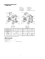
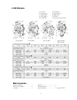
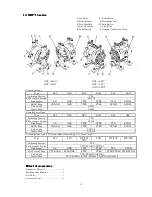
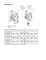
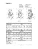
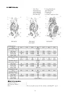
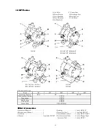
                                                                                                      A: Air Valve                      F : Pump Base (Stand) 
                                                                                                      B: Reset Button                G: Discharge Port 
                                                                                                      C: Out Manifold              H: Intake Port 
                                                                                                      D: Out Chamber                I: Lift Point 
                                                                                                      E: In Manifold                    J: Ground Connection Point 


                      NDP-50BA

                                            NDP-50BS

                                                        NDP-50BP


    NDP-50BF

                                                        NDP-50BV


    •Aluminum type 

Type 

BAC 

BAN 

BAE 

BAV 

BAT 

BAH 

BAS 

Switching Portion 

ADC12 

Fluid contact Portion 

ADC12 

Diaphragm 

CR 

NBR 

EPDM 

FPM 

PTFE 

TPEE 

TPO 

Ball/O Ring 

CR/NBR 

NBR 

EPDM 

FPM 

PTFE 

PTFE 

EPDM 

Valve Seat 

CR 

NBR 

EPDM 

FPM 

A5056 

TPEE 

TPO 

Center Disk 

A5056 

    •Stainless-steel type ([ ]: Cast iron type) 

Type 

BSC 

[BFC] 

BSN 

[BFN] 

BSE 

[BFE] 

BSV 

[BFV] 

BST 

[BFT] 

BSH 

[BFH] 

BSS 

[BFS] 

Switching Portion 

ADC12 

Fluid contact Portion 

SCS14 [FC250] 

Diaphragm 

CR 

NBR 

EPDM 

FPM 

PTFE 

TPEE 

TPO 

Ball/O Ring 

CR/NBR 

NBR 

EPDM 

FPM 

PTFE 

PTFE 

EPDM 

Valve Seat 

CR 

NBR 

EPDM 

FPM 

SUS316 

TPEE 

TPO 

Center Disk 

SUS316 

    •Polypropylene type ([ ]: Polyvinylidene fluoride type) 

Type 

BPC 

BPN 

BPE 

[BVE] 

BPV 

[BVV] 

BPT 

[BVT] 

BPH 

BPS 

[BVS] 

Switching Portion 

ADC12 

Fluid contact Portion 

PPG [PVDF] 

Diaphragm 

CR 

NBR 

EPDM 

FPM 

PTFE 

TPEE 

TPO 

Ball/O Ring 

CR/NBR 

NBR 

EPDM 

FPM 

PTFE 

PTFE 

EPDM 

Valve Seat 

PP [PTFE] 

Center Disk 

PPG (SCS13) [PVDF(SCS13)] 


List of accessories

List of accessories

List of accessories

List of accessories    

    •Operation Manual·························1 
    •Maintenance Manual·····················1 
    •Bolt············································4 (for securing the pump with the cushions, excluding BP

  type.) 

Summary of Contents for DP-10/12 series

Page 1: ...R YAMADA AIR OPERATED DIAPHRAGM PUMPS OPERATED DIAPHRAGM PUMPS OPERATED DIAPHRAGM PUMPS OPERATED DIAPHRAGM PUMPS NDP 5 series DP 10 12 series NDP 10 12 series NDP 15 series NDP 20 series NDP 25 series NDP 40 series NDP 50 series NDP 80 series DP F series Doc No NDP002U 18 Issue 1998 6 Revised 2008 12 ...

Page 2: ... YAMADA CORPORATION will keep on file for review for following Technical documentation operating instructions as required plans description of measures designed to ensure conformity other technical documentation Importer Distributor in EU Name of company YAMADA EUROPE B V Address Aquamarijnstraat 50 7554 NS Hengelo O The Netherlands This product is certificated in TUV Rheinland about safety Certif...

Page 3: ...olypropylene or fluorine resin depending on the model you have selected according to the type of fluid to be pumped The diaphragms are made of a plastic material suitable for the model For safe operation For safe operation For safe operation For safe operation This document contains information vital for safe and efficient operation of this product Before using the pump be sure to read this docume...

Page 4: ... one of these pumps depending upon the casing material of the model you are using is as follows Metal casing aluminum stainless steel forged iron 0 7MPa 7kgf cm2 Plastic casing polypropylene fluorine resin 0 7MPa 7kgf cm2 0 5MPa for the DP 05F until DP 20F 0 7MPa for the DP 25F 38F If the pressure of the compressed air and fluid exceeds the above applicable maximum permissible pressure specified a...

Page 5: ...t near the place of installation of this product should be properly insulated to prevent conduction with each other Do NOT operate heating devices that create flames or have heating filaments anywhere near the pump or the piping If there are flammable gases in the air while the pump is operating do NOT switch electric appliances on and off Do NOT operate a gasoline engine at the work site Restrict...

Page 6: ...ng the product or leakage of fluid When working in the vicinity of pumping of fluid with this product be sure to wear protective gear goggles mask etc When using this product observe the relevant regulatory rules concerning fire prevention labor safety standards etc If you have any questions on the operation of this product method of connection or installation contact your dealer or our regional o...

Page 7: ...on 4 1 Connecting fluid piping 23 4 2 Connecting air piping 24 5 Operation 5 Operation 5 Operation 5 Operation 5 1 Method of operation 25 5 2 Flow adjustment 25 5 3 Shutdown 26 5 4 Releasing the pressure 26 6 Method of cleaning 6 Method of cleaning 6 Method of cleaning 6 Method of cleaning 27 7 Daily check 7 Daily check 7 Daily check 7 Daily check 28 8 Troubleshooting 8 Troubleshooting 8 Troublesh...

Page 8: ...SCS14 PPG PVDF ACETAL Diaphragm PTFE Flat Valve SUS316 PTFE O Ring PTFE Valve Seat SUS316 PPG PVDF ACETAL Center Disk A5056 SUS316 PPG SUS304 PVDF SUS304 ACETAL SUS304 Only PTFE diaphragm is setup in NDP 5 series List of accessories List of accessories List of accessories List of accessories Operation Manual 1 Maintenance Manual 1 Air Valve 1 Accessory Tool 1 FPT FVT FDT 2 A Air Valve B Reset Butt...

Page 9: ...4 Diaphragm CR NBR PTFE TPEE TPO EPDM Ball O Ring CR NBR NBR PTFE PTFE EPDM EPDM Valve Seat SUS316 Center Disk SUS316 Polypropylene type Drum type B B B B Type BPC BPN BPT BPH BPS BPE Switching Portion ADC12 Fluid contact Portion PPG Diaphragm CR NBR PTFE TPEE TPO EPDM Ball O Ring CR NBR NBR PTFE PTFE EPDM EPDM Valve Seat CR NBR PPG PPG PPG PPG Center Disk PPG SUS304 List of accessories List of ac...

Page 10: ...10 BPC NDP 10 BPN NDP 10 BPT NDP 10 BPS NDP 10 BPH NDP 10 BPE Polypropylene type Type BPC BPN BPT BPH BPS BPE Switching Portion PPS Fluid contact Portion ADC12 Diaphragm CR NBR PTFE TPEE TPO EPDM Ball O Ring CR NBR NBR PTFE PTFE EPDM EPDM Valve Seat CR NBR PPG PPG PPG PPG Center Disk PPG SUS304 List of accessories List of accessories List of accessories List of accessories Operation Manual 1 Maint...

Page 11: ...steel type Type BSC BSN BST BSH BSS BSE Switching Portion PPS Fluid contact Portion SCS14 Diaphragm CR NBR PTFE TPEE TPO EPDM Ball O Ring CR NBR NBR PTFE PTFE EPDM EPDM Valve Seat SUS316 Center Disk SUS316 Polypropylene type Polyvinylidene fluoride type Acetal type Type FPC FPN FPT FVT FDT FPH FPS FVS FPE FVE Switching Portion PPS Fluid contact Portion PPG PVDF ACETAL Diaphragm CR NBR PTFE TPEE TP...

Page 12: ...AS BAH Switching Portion ADC12 Fluid contact Portion ADC12 ADC12 AC2A SGP Diaphragm CR NBR EPDM FPM PTFE TPO TPEE Ball O Ring CR NBR NBR EPDM FPM PTFE EPDM PTFE Valve Seat SMS1025 Center Disk SUS316 A5056 SUS316 Stainless steel type Cast iron type Type BSC BFC BSN BFN BSE BFE BSV BFV BST BFT BSS BFS BSH BFH Switching Portion ADC12 Fluid contact Portion SCS14 S45C Diaphragm CR NBR EPDM FPM PTFE TPO...

Page 13: ...T BPH BPS BVS Switching Portion ADC12 Fluid contact Portion PPG PVDF Diaphragm CR NBR EPDM FPM PTFE TPEE TPO Ball O Ring CR NBR NBR EPDM FPM PTFE PTFE EPDM Valve Seat PPG PVDF Center Disk PPG SUS303 PVDF SUS303 List of accessories List of accessories List of accessories List of accessories Operation Manual 1 Bushing 1 only NDP 20 Maintenance Manual 1 Accessory Tool 2 only BP and BV Air Valve 1 Suc...

Page 14: ...BSC BFC BSN BFN BSE BFE BSV BFV BST BFT BSH BFH BSS BFS Switching Portion ADC12 Fluid contact Portion SCS14 Diaphragm CR NBR EPDM FPM PTFE TPEE TPO Ball O Ring CR NBR NBR EPDM FPM PTFE PTFE EPDM Valve Seat CR NBR EPDM FPM SUS316 TPEE TPO Center Disk SUS316 Polypropylene type Type BPC BPN BPE BVE BPV BVV BPT BVT BPH BVH BPS BVS Switching Portion ADC12 Fluid contact Portion PPG PVDF Diaphragm CR NBR...

Page 15: ...N BSE BFE BSV BFV BST BFT BSH BFH BSS BFS Switching Portion ADC12 Fluid contact Portion SCS14 FC250 Diaphragm CR NBR EPDM FPM PTFE TPEE TPO Ball O Ring CR NBR NBR EPDM FPM PTFE PTFE EPDM Valve Seat CR NBR EPDM FPM SUS316 TPEE TPO Center Disk SUS316 Polypropylene type Polyvinylidene fluoride type Type BPC BPN BPE BVE BPV BVV BPT BVT BPH BPS BVS Switching Portion ADC12 Fluid contact Portion PPG PVDF...

Page 16: ... iron type Type BSC BFC BSN BFN BSE BFE BSV BFV BST BFT BSH BFH BSS BFS Switching Portion ADC12 Fluid contact Portion SCS14 Diaphragm CR NBR EPDM FPM PTFE TPEE TPO Ball O Ring CR NBR NBR EPDM FPM PTFE PTFE EPDM Valve Seat CR NBR EPDM FPM SUS316 TPEE TPO Center Disk SUS316 Polypropylene type Type BPC BPN BPE BPV BPT BPH BPS Switching Portion ADC12 Fluid contact Portion PPG Diaphragm CR NBR EPDM FPM...

Page 17: ...Fluorine resin type Type 5F 10F 20F 25F 38F Switching Portion PPS PP PE PP Fluid contact Portion PTFE Diaphragm PTFE Ball O Ring PTFE Valve Seat PTFE Center Disk PFA SUS316 List of accessories List of accessories List of accessories List of accessories Operation Manual 1 Bushing 1 only DP 25F Maintenance Manual 1 Union Air Port 1 exclude DP 5F Air Valve 1 Union Exhaust Port 1 only DP 10F 20F Silen...

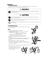
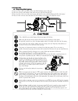
Page 18: ...lencer nipple see the appearance drawings on 1 Names of parts and materials after p 8 With some models these are already installed CAUTION CAUTION CAUTION CAUTION All of the connection parts are capped or taped for shipment Remove the caps and tapes When installing accessories make sure that no foreign matter falls into the product as it could cause malfunction of the switching portion Cover each ...

Page 19: ... 2 Installing the pump 3 2 Installing the pump 1 Decide where the pump should be installed and secure a suitable space see Fig 3 1 A to D Note Note Note Note Try to keep the suction lift as short as possible Protect diaphragm from abnormal breakage inlet pressure must be kept below the following values PTFE diaphragm 0 02MPa height 2m During operation 0 05MPa height 5m Not in operation Other diaph...

Page 20: ... specifications on p 26 When pumping a hazardous fluid hot flammable strong acid etc provide protective measures installation of a pit or sensors etc in consideration of possible leakage of fluid and post warning signs at necessary places For details see the applicable operating caution on p 4 5 and 6 WARNING WARNING WARNING WARNING If using the pump with a flammable fluid or in a flammable enviro...

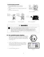
Page 21: ...nvironment such as gases in the air or the surrounding fixtures it may be a cause of fire or electric shock 3 3 3 3 3 3 3 3 1 1 1 1 Use in potentially explosive atmospheres Use in potentially explosive atmospheres Use in potentially explosive atmospheres Use in potentially explosive atmospheres 1 Your pump can be used in potentially explosive atmospheres if the symbol of Fig 3 3 1 is visible on th...

Page 22: ... operate the pump without a ground wire or otherwise not properly grounded friction caused by some fluids flowing inside the casing may generate static electricity Also depending on the type of fluid being pumped and the installation environment such as gases in the air or the surrounding fixtures it may become an ignition source resulting in a possible explosion Be careful when using tools at or ...

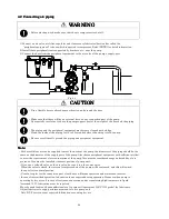
Page 23: ...lurries indicated in the main specifications attach a strainer to the pump to stop larger particles Otherwise such particles may cause a malfunction If depending upon the place of pump installation the volume of the pumped fluid changes drastically install a relief valve on the discharge side and bring the pressure down below the maximum permissible value If owing to a change in the volume of flui...

Page 24: ...d the piping and peripheral equipment Note Note Note Note So that sufficient air can be supplied to meet the needs of the pump the diameter of the piping should be the same as the diameter of the supply port of the pump Also choose peripheral equipment with sufficient airflow to meet the requirement of air consumption of the pump Also must be considered usage and stability of air pressure Also mus...

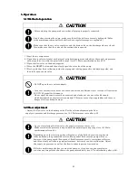
Page 25: ...sed turbine oil none addition class 1 turbine oil equivalent ISO VG 32 grade for lubricants Do not apply lubricants more than required and also do not use any other lubricants which designated on this instruction manual This may cause of pump problem and there is danger of serious bodily damage 5 2 Flow adjustment 5 2 Flow adjustment 5 2 Flow adjustment 5 2 Flow adjustment Adjust the flow valve on...

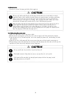
Page 26: ...e such as bending of the center rod After finishing your work purge the remaining fluid from the pump see 6 Method of cleaning on p 27 5 4 Releasing the pressure 5 4 Releasing the pressure 5 4 Releasing the pressure 5 4 Releasing the pressure 1 Make sure that the air valve of the pump is closed 2 Shut down the air compressor or close the valve on the air supply side of the peripheral equipment 3 C...

Page 27: ...om the discharge side and attach different hoses to the suction side and the discharge side for cleaning 4 Be ready with a vessel with cleaning solution select cleaning solution appropriate for the type of fluid pumped and then connect the suction side and the discharge side hoses of the pump 5 Operate a pump by starting air pressure slowly and let the cleaning solution circulate for sufficient cl...

Page 28: ...eck and clean 8 2 Pump runs but fluid does not come out 8 2 Pump runs but fluid does not come out 8 2 Pump runs but fluid does not come out 8 2 Pump runs but fluid does not come out Cause Cause Cause Cause Action to be taken Action to be taken Action to be taken Action to be taken The suction lift or discharge head is long Confirm the piping configuration and shorten the length The discharge side ...

Page 29: ...Irregular vibration 8 7 Irregular vibration 8 7 Irregular vibration Cause Cause Cause Cause Action to be taken Action to be taken Action to be taken Action to be taken The supply air pressure is too high Adjust the supply air pressure The spool oscillates and occurs ball chattering Adjust the supply air pressure and exhaust pressure Connection parts and pump mounting are loose Check each connectio...

Page 30: ...rating Ambient Temperature Range Fluid Temp 0 100 C 32 212 F 0 60 C 32 140 F Operating Noise 72dB Weight 1 6kg 2 7kg 1 4kg 1 7kg DP DP DP DP 10 10 10 10 12 12 12 12 series series series series DP 10 12 Type BA BS BP Nominal Diameter 3 8 10mm Suction Port Rc3 8 DP 10 BSP 1 2 DP 12 Fluid Connection Discharge Port Rc3 8 DP 10 BSP 1 2 DP 12 E C Countries BSP3 8 E C Countries BSP1 2 Other Countries Rc3...

Page 31: ... 3 kg NDP NDP NDP NDP 15 series 15 series 15 series 15 series NDP 15 Type BA BS FP FVT FDT Nominal Diameter 1 2 15mm Suction Port Fluid Connection Discharge Port Rc1 2 E C Countries BSP1 2 Other Countries Rc1 2 Supply Port Rc1 4 Air Connection Exhaust Port Rc3 8 Normal Air Pressure 0 2 0 7MPa 2 7kgf cm2 0 2 0 7MPa 2 7kgf cm2 Maximum Discharge Pressure 0 7MPa 7kgf cm2 0 7MPa 7kgf cm2 Discharge Volu...

Page 32: ... 0 70 C 32 158 F EPDM 20 80 C 1 176 F TPEE TPO PTFE 0 100 C 32 212 F FPM 10 120 C 14 248 F 0 60 C 32 140 F Operating Noise 89dB 89dB Weight 9 0kg 11 2kg 1 14 0kg 8 0kg 1 Drum type NDP NDP NDP NDP 25 metal type series 25 metal type series 25 metal type series 25 metal type series NDP 25 Type BA BAT BS BST BF BFT Nominal Diameter 1 25mm Suction Port Fluid Connection Discharge Port Rc1 Supply Port Rc...

Page 33: ... 40 Type BA BAT BS BST BF BFT BP BV BPT BVT Nominal Diameter 1 1 2 40mm Suction Port Fluid Connection Discharge Port Equivalent to JIS flange 10K40A Rc1 1 2 Equivalent to JIS flange 10K40A Supply Port Rc1 2 Air Connection Exhaust Port Rc1 Normal Air Pressure 0 2 0 7MPa 2 7kgf cm2 0 2 0 7MPa 2 7kgf cm2 Maximum Discharge Pressure 0 7MPa 7kgf cm2 0 7MPa 7kgf cm2 Discharge Volume Stroke 2800mL 1400mL ...

Page 34: ...76 F TPEE TPO PTFE 0 100 C 32 212 F FPM 10 120 C 14 248 F 0 60 C 32 140 F PP 0 80 C 32 176 F PVDF Operating Noise 82dB 82dB Weight 36kg 63kg 64kg 37kg 42kg NDP NDP NDP NDP 80 series 80 series 80 series 80 series NDP 80 Type BA BAT BS BST BF BFT BP BPT Nominal Diameter 3 80mm Suction Port Fluid Connection Discharge Port Equivalent to JIS flange 10K80A Rc3 Equivalent to JIS flange 10K80A Supply Port...

Page 35: ... 2 0 7MPa 2 7kgf cm2 Maximum Discharge Pressure 0 5MPa 5kgf cm2 0 7MPa 7kgf cm2 Discharge Volume Stroke 13mL 65mL 150mL 400mL 700mL Maximum Discharge Volume 10L min 25L min 50L min 90L min 95L min Maximum Air Consumption 170 L min ANR 250 L min ANR 350 L min ANR 1200 L min ANR 1500 L min ANR Slurry Limitation Do not use the flat valve type pump for the liquids with slurry 1mm or less 2mm or less 3...

Page 36: ...and dimensions 10 2 1 NDP 10 2 1 NDP 10 2 1 NDP 10 2 1 NDP 5 series 5 series 5 series 5 series NDP NDP NDP NDP 5FAT 5FAT 5FAT 5FAT NDP NDP NDP NDP 5FST 5FST 5FST 5FST NDP NDP NDP NDP 5FPT FVT 5FPT FVT 5FPT FVT 5FPT FVT FDT FDT FDT FDT 10 2 2 DP 10 2 2 DP 10 2 2 DP 10 2 2 DP 10 series 10 series 10 series 10 series ...

Page 37: ...0 12 10 12 series series series series DP DP DP DP 10 10 10 10 12 12 12 12BA BA BA BA DP DP DP DP 10 10 10 10 12 12 12 12BS BS BS BS DP DP DP DP 10 10 10 10 12 12 12 12BP BP BP BP BSP for DP12 BSP for DP12 BSP for DP12 BSP for DP12 BSP for DP12 BSP for DP12 ...

Page 38: ...P DP 10 10 10 10 12 12 12 12BS BS BS BS 10 2 3 NDP 10 2 3 NDP 10 2 3 NDP 10 2 3 NDP 10 10 10 10 12 12 12 12 series series series series N N N NDP DP DP DP 10 10 10 10 12 12 12 12BP BP BP BP BSP for BDP12 BSP for BDP12 BSP for BDP12 BSP for BDP12 BSP for NDP12 BSP for NDP12 ...

Page 39: ...0 2 10 2 4 4 4 4 NDP NDP NDP NDP 15 series 15 series 15 series 15 series NDP NDP NDP NDP 15BA 15BA 15BA 15BA NDP NDP NDP NDP 15B 15B 15B 15BS S S S NDP NDP NDP NDP 15FP 15FP 15FP 15FP FVT FVT FVT FVT FDT FDT FDT FDT ...

Page 40: ...40 10 2 10 2 10 2 10 2 5 5 5 5 NDP NDP NDP NDP 20 series 20 series 20 series 20 series NDP NDP NDP NDP 20BA 20BA 20BA 20BA NDP NDP NDP NDP 20BS 20BS 20BS 20BS NDP NDP NDP NDP 20BP 20BP 20BP 20BP ...

Page 41: ...41 B B B BDP DP DP DP 20BA 20BA 20BA 20BA 10 2 10 2 10 2 10 2 6 6 6 6 NDP NDP NDP NDP 25 series 25 series 25 series 25 series NDP NDP NDP NDP 25BA 25BA 25BA 25BA NDP NDP NDP NDP 25BS 25BS 25BS 25BS ...

Page 42: ...42 NDP NDP NDP NDP 25BF 25BF 25BF 25BF NDP NDP NDP NDP 25BP 25BP 25BP 25BP NDP NDP NDP NDP 25BV 25BV 25BV 25BV ...

Page 43: ...43 10 2 10 2 10 2 10 2 7 7 7 7 NDP NDP NDP NDP 40 series 40 series 40 series 40 series NDP NDP NDP NDP 40BA 40BA 40BA 40BA NDP NDP NDP NDP 40BS 40BS 40BS 40BS NDP NDP NDP NDP 40BF 40BF 40BF 40BF ...

Page 44: ...44 NDP NDP NDP NDP 40 40 40 40BP BP BP BP NDP NDP NDP NDP 40BV 40BV 40BV 40BV ...

Page 45: ...45 10 2 10 2 10 2 10 2 8 8 8 8 NDP NDP NDP NDP 50 series 50 series 50 series 50 series NDP NDP NDP NDP 50B 50B 50B 50BA A A A NDP NDP NDP NDP 50BS 50BS 50BS 50BS ...

Page 46: ...46 NDP NDP NDP NDP 50BF 50BF 50BF 50BF NDP NDP NDP NDP 50BP 50BP 50BP 50BP NDP NDP NDP NDP 50BV 50BV 50BV 50BV NDP NDP NDP NDP 50B 50B 50B 50BV V V V ...

Page 47: ...47 10 2 10 2 10 2 10 2 9 9 9 9 NDP NDP NDP NDP 80 series 80 series 80 series 80 series NDP NDP NDP NDP 8 8 8 80B 0B 0B 0BA A A A NDP NDP NDP NDP 80BS 80BS 80BS 80BS ...

Page 48: ...48 NDP NDP NDP NDP 80BF 80BF 80BF 80BF NDP NDP NDP NDP 80BP 80BP 80BP 80BP ...

Page 49: ...0 10 10 10 DP DP DP DP F series F series F series F series DP DP DP DP 5F 5F 5F 5F DP DP DP DP 10F PT FEMALE 10F PT FEMALE 10F PT FEMALE 10F PT FEMALE DP DP DP DP 10F JIS 10K 10A 10F JIS 10K 10A 10F JIS 10K 10A 10F JIS 10K 10A ...

Page 50: ...50 DP DP DP DP 20F PT FEMALE 20F PT FEMALE 20F PT FEMALE 20F PT FEMALE DP DP DP DP 20F JIS 10K 20A 20F JIS 10K 20A 20F JIS 10K 20A 20F JIS 10K 20A DP DP DP DP 25F 25F 25F 25F ...

Page 51: ... 38F 38F 38F CAUTION CAUTION CAUTION CAUTION Due to improvement or modification of products dimensions are should be changed without prior notice Please contact your dealer or our regional office for detailed information ...

Page 52: ...sed until a max of 5Bar Above 60ºC max pressure 5Bar Above 60ºC max pressure 5Bar Above 60ºC max pressure 5Bar Above 60ºC max pressure 5Bar 10 10 10 10 3 3 3 3 1 NDP 1 NDP 1 NDP 1 NDP 5 serie 5 serie 5 serie 5 series s s s 10 10 10 10 3 3 3 3 2 2 2 2 DP DP DP DP 10 10 10 10 series series series series 10 10 10 10 3 3 3 3 2 2 2 2 B B B B DP DP DP DP 10 12 10 12 10 12 10 12 series series series seri...

Page 53: ...N NDP DP DP DP 10 12 10 12 10 12 10 12 series series series series 10 10 10 10 3 3 3 3 4 4 4 4 NDP NDP NDP NDP 1 1 1 15 series 5 series 5 series 5 series 10 10 10 10 3 3 3 3 5 5 5 5 NDP NDP NDP NDP 20 20 20 20 series series series series ...

Page 54: ...54 10 10 10 10 3 3 3 3 6 6 6 6 NDP NDP NDP NDP 25 25 25 25 series series series series 10 10 10 10 3 3 3 3 7 7 7 7 NDP NDP NDP NDP 40 40 40 40 series series series series ...

Page 55: ...55 10 10 10 10 3 3 3 3 8 8 8 8 NDP NDP NDP NDP 50 50 50 50 series series series series 10 10 10 10 3 3 3 3 9 9 9 9 NDP NDP NDP NDP 80 80 80 80 series series series series ...

Page 56: ...56 10 10 10 10 3 3 3 3 10 10 10 10 DP DP DP DP F F F F series series series series ...

Page 57: ...ue is to be used Note Note Note Note Method of measurement of performance curve Measuring instruments and procedure Conditions a Supplied air pressure Maintaining preset pressure b Liquid pumped Fresh water c Temperature Ambient d Condition of suction Flat suction 0 meter head e Measuring system System A Converting weight of discharged fluid to volume System B By liquid meter ...

Page 58: ...g FAX Sheet Name of your firm Name of person in charge Department Address Telephone Fax MODEL No Product name Product No Date of product Period of use From to SERIAL No Lot No Operating conditions Indoor Outdoor Frequency of operation Continuous Intermittent Hours day week month Date of purchase Name of dealer Operating air pressure MPa Discharge pressure MPa Discharge volume L min Stroke Suction ...

Page 59: ...symbols 12 Warning symbols 12 Warning symbols 12 Warning symbols BEWARE HIGH TEMPERATURE ELECTRIC SHOCK POISON FLAMMABLE CORROSION EXPLOSION General warnings cautions and danger notifications FIRE STRICTLY PROHIBITED ...

Page 60: ...rized service personnel 5 Malfunction arising from modification of the product by other than authorized service personnel 6 Wear and tear of parts that must be regularly replaced in the course of normal operation such as diaphragms valve seats balls air switch sleeve valves and O rings 7 Malfunction and or damage due to transportation moving or drop page of the product after purchase 8 Malfunction...

Reviews: