36
YA3805-201006
EN
NL
EN
A.10
Choose the installation type suitable for the
surface on which the Sona will be installed.
WARNING
A surface mount can only be done
when the existing surface is made of at least 15
cm (5.9”) solid concrete.
DEEP
mount (in existing ground): continue with
part B
SURFACE
mount (on top of existing surface):
continue with part C
B. DEEP MOUNT
NOTICE
Make sure the necessary preparations
have been made according to chapter A.
B.1
Dig out the holes for the anchors, according to
the indicated dimensions.
B.2
Align the moulds according to the dimensions
shown in the image.
B.3
Screw the anchors in place according to the
dimensions shown in the image.
B.4
Pour the concrete to the indicated height and
wait until it has hardened. One nut and washer
per anchor will stay in the concrete, this has been
accounted for in the amount of parts included in
the package.
B.5
Unscrew the upper nuts from the anchors and
remove the moulds.
NOTICE
You can now continue the installation by
following the steps in chapter D.
C. SURFACE MOUNT
NOTICE
Make sure the necessary preparations
have been made according to chapter A.
C.1
Align the moulds according to the image.
C.2
Drill three holes per mould according to the
instructions of the used chemical anchor.
C.3
Insert the chemical anchors according to their
instructions.
D. INSTALLATION
CAUTION
The people installing the product
should wear the required protection and clothing.
D.1
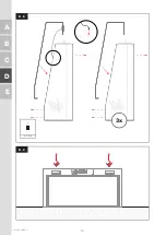
Remove the polyester caps from the arches
and remove the protection material.
D.2
Fasten a nut to each anchor and add an
adjustment fl ange to each anchor.
D.3
Lift up the arch with the crane and lower it onto
the anchors. Make sure the main power cable runs
through the indicated hole. Fasten the arch to the
anchors, but do not fully tighten yet.
NOTICE
Keep the arch supported until the two
arches have been connected on top.
D.4
Lift up the other arch and lower onto the
anchors. Fasten the arch to the anchors, but do not
fully tighten yet.
D.5
Align the tops of the arches by using the three
bolts at the bottom of each arch.
D.6
Connect the arches at the top, but do not fully
tighten yet.
D.7
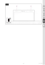
Put the polyester caps in place by sliding them
on top of the arches.
D.8
Tighten the polyester caps to the steel frame
with the L-clamps.
D.9
Tighten all bolts/nuts on the top and the
bottom of the frame.
D.10
Connect the polyester caps to the top of the
frame.
D.11
Connect the speaker cables in the top of the
Sona.
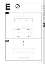
D.12
Run the camera plate cable through the
cable protection tube inside the Sona, towards
the computer. Place the camera plate in place and
fasten.
D.13
Place the side plate with the button near the
computer. Connect all cables to the computer: A.
button, B. camera and C. power.
Summary of Contents for Sona YA3500
Page 1: ...EN NL Installation instructions Installatievoorschrift YA3805 Yalp Toro ...
Page 5: ...5 YA3805 201006 A B C D E A 811 mm 31 9 1650 mm 65 0 300 mm 11 8 13 62 m 536 A 2 ...
Page 8: ...8 YA3805 201006 1 5 m 5 ft 2 m 78 7 X 200 mm 7 9 A 4 A 5 A C E B D A ...
Page 9: ...9 YA3805 201006 A B C D E A A 6 ...
Page 11: ...11 YA3805 201006 A B C D E A A 8 A 9 Data 15 m 3x ...
Page 12: ...12 YA3805 201006 150 mm 6 A 10 C E B D A ...
Page 18: ...18 YA3805 201006 A C E B D D D 3x D 1 ...
Page 19: ...19 YA3805 201006 A B C D E D 100 204 8x D 2 ...
Page 20: ...20 YA3805 201006 A C E B D D D 3 ...
Page 22: ...22 YA3805 201006 A C E B D D WARNING D 6 NOTICE PE N L ...
Page 23: ...23 YA3805 201006 A B C D E D A A C B B C CLIC K CLICK D 7 ...
Page 24: ...24 YA3805 201006 A C E B D D 3x D 8 D 9 BIT TX40 ...
Page 25: ...25 YA3805 201006 A B C D E D D 10 0850 2006 2003 8x ...
Page 26: ...26 YA3805 201006 A C E B D D 11 ...
Page 27: ...27 YA3805 201006 A B C D E E E 1 E 2 E ...
Page 28: ...28 YA3805 201006 A C E B D E E 3 E 4 ...


