background image

EN_Installation manual_Memo_v2.9


- 6 -

4  Foundation

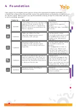
Yalp suggests four standard mounting options. Choose the appropriate foundation method for your 

situation. For surfaces other than concrete, such as tiles, please contact our foundation installation team 

for specific support. Please request your specific installation drawing at Yalp. This information will come 

to you in a separate document.

Product nr.

When used?

Description

YA3930D

Used outdoor. The anchors are deposited 

together with the concrete into the 

ground. Please note; it is important to 

pour the concrete one week before the 

Memo is mounted.

-Deep mount-

7x deep mounting ground 

anchors.  

Included: PVC tubes to conduct 

the cables.

YA3930S1

Cables are milled in the floor.

Option for indoor use only, 

used in 

combination with wet pour.

-Surface mount milling-

7x installation plate and anchors

Included: protective tubes to 

conduct wires. Ø40mm with 

cord. [1.6”]

YA3930S2

Suitable for indoor use only on 

combination with wet poor. Option 

for places in with milling in the floor is 

impossible.

-Surface mount without milling-

7x installation plates and 

anchors. 

Included: protective tubes to 

conduct wires. Ø40mm with 

cord. [1.6”] The cables will be in 

a dome on the floor. (Plates are 

higher leveled than YA3930S1.)

YA3930S3

For definitive outdoor placing (tiles on 

top) or for exhibitions, when there  can 

not be milled any deeper than 150mm 

(1.6yards) into the ground. To be placed 

in sand or on flat concrete. 

-Spider mount-

7x installation plates and steel 

tube mounted together as one 

solid construction. The spider 

frame is positioned 100-150 mm  

underground. [3.9-5.9”]Tiles can 

be placed over the construction.

YA3930E

Temporary fixation. No milling or 

attachment to floor

-Exhibition-

Ask Yalp for possibilities, several 

options available

Summary of Contents for Memo

Page 1: ...15 February 2019 Version 2 9 Memo Installation manual ...

Page 2: ... please contact us Have fun with the product 1 Preparation 3 2 Memo isometric view 4 3 Memo posts isometric view 5 4 Foundation 6 5 Cable installation 7 6 Installation Field preparation 8 7 Electronics Information 9 8 Installation Electronics 10 9 Changing heads 12 10 Removing master post head 13 11 Removing Basic post head 18 12 Installing new heads 21 13 Adding knee entrapment prevention 22 14 D...

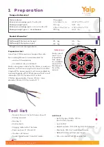
Page 3: ... bit holder Saw 1 Preparation 3900 Obstakelvrije ruimte 9680 Kunstgras 8000 840 840 1500 Transport information Crate material Dimensions package posts L x B x H Package weight posts Dimensions package grass misc L x B x H Package weight grass miscellaneous Product information Netto weight Memo master post Netto weight Memo basic post Weights and sizes are approximate Pine wood 1 2 x 0 8 x 1 4 m 3 ...

Page 4: ...EN_Installation manual_Memo_v2 9 4 2 Memo isometric view ...

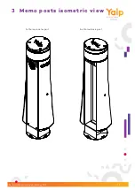
Page 5: ...EN_Installation manual_Memo_v2 9 5 3 Memo posts isometric view 1x Memo master post 6x Memo basic post ...

Page 6: ...pour Surface mount milling 7x installation plate and anchors Included protective tubes to conduct wires Ø40mm with cord 1 6 YA3930S2 Suitable for indoor use only on combination with wet poor Option for places in with milling in the floor is impossible Surface mount without milling 7x installation plates and anchors Included protective tubes to conduct wires Ø40mm with cord 1 6 The cables will be i...

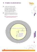
Page 7: ...r group and has a minimum extra length of 1 5 m 1 6yards above the ground 2 Prepare the surface as described in the costom made fundation document for your location Below an example of a curbstone fininsh Make sure the power connection is located exactly in the middle of the circle 5 Cable installation 230v assembled on a separate group with at least 1 5 m 1 6 yards above ground Outside diameter c...

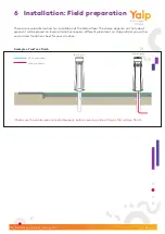
Page 8: ... will be placed on Every alternative requires different placement so Yalp profides you with a costumized fundation sheet for your situation 6 Installation Field preparation Make sure the cables are connected properly before covering and putting on the surface finsih Example of surface finish Basic post Master post UTP powercable 230V powercable ...

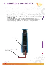
Page 9: ...ctronic parts The power cable needs to be connected to the power socket on the mounting panel by a certified electrician Solely use the supplied cable Ecomate to power net be used between the power socket and the safety transformer The power cable needs to be connected to the blue power socket norm 2P earth contact box of class IP44 This power supply MUST be assembled on separate group with a 30mA...

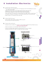
Page 10: ...de the button must be positioned Take sure the hats of the basic posts are pointing to the middle Stickers are positioned on the hats of the posts which gives instruction and are pointing in the right direction Bolt all the posts to the ground with anchor bolts 2 Connecting the basic posts Lead the power data cable through the rubber ring up to the touchscreen unit and connect them 3 Connecting th...

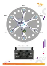
Page 11: ...EN_Installation manual_Memo_v2 9 11 Post 2 Post 4 Post 7 Post 6 Post 5 Post 3 Post 2 Post 7 Post 3 Post 6 Post 4 Post 5 Front side Yin computer as seen from above section view Bottom side yin computer ...

Page 12: ...ts with changing removing the head of the master post and continues with changing removing the head of the basic post and ends with insalling the new heads Tool list 6x PVC pipes Diameter 32mm lenght 2 90m 0 1 2 length 3 17yards cordless powered drill driver security torx 40 bit with hole cut out hex size 5 loctite 243 9 Changing heads ...

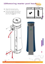
Page 13: ...er frontplate PCS 160 212 1 4 1 Remove the main power from the product by removing the power plug 2 Remove the frontplate of the master post by removing the M8x20 100 210 bolts 4x Then move the front cap in the right direction as showned below 10 Removing master post head 2 3 1 ...

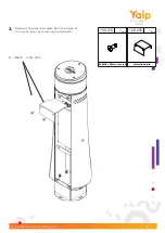
Page 14: ...stallation manual_Memo_v2 9 14 protection plate PCS 160 252 Bolt M8 x 20 mm secured PCS 100 210 1 2 2x M8x20 100 210 3 Remove the protection plate from the frame of the master post by removing the two bolts ...

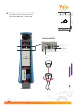
Page 15: ...upply Yin computer Data powercable 1m PCS 100 127 1 To antenna s Button Ethernet To touchscreen unit upper side yin computer 4 Disconnect the touchscreen unit from the yin computer by first twisting and then pulling out the cable as showed below socket ...

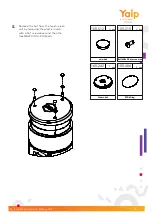
Page 16: ... 160 242 EPDM ring PCS 100 406 1 1 cap hat PCS 100 512 Bolt M8 x 20 mm secured PCS 100 210 3 4 5 Remove the hat from the touchscreen unit by removing the plastic inserts with a flat screwdriver and then the tree M8x20 100 210 bolts DETAIL G SCALE 1 5 ...

Page 17: ...9 17 Hexagon M8x12 PCS 100 233 4 Touchscreen PCS 160 100 1 A DETAIL A SCALE 2 5 A DETAIL A SCALE 2 5 Connector on left side Remove the bolts 6 Remove the touchscreen unit from the steel frame by removing the four M8x12 100 233 bolts ...

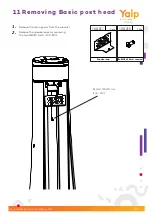
Page 18: ...v2 9 18 Speaker cap PCS 160 011 Bolt M8 x 20 mm secured PCS 100 210 2 2 2x Bolt M8x20 mm 100 210 1 Remove the main power from the product 2 Remove the speakercaps by removing the two M8x20 bolts 100 210 11 Removing Basic post head ...

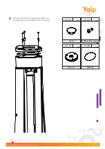
Page 19: ...ion manual_Memo_v2 9 19 Memo hat PCS 160 242 EPDM ring PCS 100 406 1 1 cap hat PCS 100 512 Bolt M8 x 20 mm secured PCS 100 210 3 4 3 Remove the hat from the touchscreen unit by removing the tree M8x20 100 210 bolts ...

Page 20: ... 20 Hexagon M8x12 PCS 100 233 Touchscreen PCS 160 100 1 4 4 Remove the touchschreen unit from the steel frame by removing the four M8x10 100 233 bolts 5 Disconnect the cable by first twisting and then pulling the cable as showed below ...

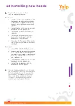
Page 21: ... of the master post by removing the M8x20 100 210 bolts 4x Basic post 1 connect the cable to the touchscreen 2 place the touchschreen unit to the steel frame with the M8x10 100 233 bolts 4x Apply loctite adhesive right before fastening the bolts to the touchscreen unit see page 21 3 connect the hat to the touchscreen with the M8x20 100 210 bolts 3x 4 connect the speakercaps with the M8x20 bolts 10...

Page 22: ... shown in figure 2 2 Connect the hole closers with four bolts M8x20x24 100 210 Hole closer 160 325 two per post facing each other to prevent knee entrapment Figure 2 Placement of the hole closers on a memo basic post Figure 1 Memo post with hole closers Lassam hole closer2 PCS 160 325 Bolt M8 x 20 mm secured PCS 100 210 4 2 ...

Page 23: ...EN_Installation manual_Memo_v2 9 23 Ø 9680mm 10 6yards obstacle free zone 14 Dimensions Memo 1 5 0 0 m m 1 6 y a r d s 45 8 8 7yards 3 3yards 3 3 y a r d s 23 9 ...

Page 24: ...EN_Installation manual_Memo_v2 9 24 1161 1161 331 331 Master Basic 15 Dimensions Memo posts 4 57 1 130 3 4 57 1 130 3 ...

Page 25: ...plier of play sets and sports products we are aware of the social role that we play We take responsibility on the core themes of ISO 9001 2008 certified quality management system ISO 14001 2004 certified environmental management system Maintenance For maintenance we refer to our maintanance instruction Service and support If you have any questions please contact us at Yalp Support Team E service y...

Page 26: ...d support yalp nl into my yalp nl new remote tool web ad dress and replaced Sona for Memo 2x in chapter 10 Installa tion 3G Sim card Added chapter 12 Adding extra plates to prevent knee entrapment Added Do not yet connect the plug to step 3 in Chapter 9 v2 5 01 08 2017 Removed chapter 15 Warranty v2 6 04 08 2017 Removed foundation appendices because these are separate documents now v2 7 18 08 2017...

Reviews: