background image


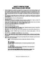
SAFETY PRECAUTIONS

SAFETY PRECAUTIONS

MAINTENANCE AND REPAIR

MAINTENANCE AND REPAIR

••

The  S

The  Servic

ervice  Manu

e  Manuals  ar

als  are  updat

e  updated  on  a  r

ed  on  a  regular 

egular basis

basis,  but  m

,  but  may  not  r

ay  not  refle

eflect  rec

ct  recent  des

ent  design  ch

ign  changes  t

anges  to  the

o  the

product. Updated technical service information may be available from your local authorized Yale

product. Updated technical service information may be available from your local authorized Yale

®

®

 dealer.

 dealer.

Service  Manuals  provide  general  guidelines  for  maintenance  and  service  and  are  intended  for  use  by

Service  Manuals  provide  general  guidelines  for  maintenance  and  service  and  are  intended  for  use  by
trained and experienced technicians. Failure to properly maintain equipment or to follow instructions con-

trained and experienced technicians. Failure to properly maintain equipment or to follow instructions con-
tained in the Service Manual could result in damage to the products, personal injury, property damage or 

tained in the Service Manual could result in damage to the products, personal injury, property damage or 
death.

death.

••

When li

When liftin

fting parts o

g parts or assem

r assemblies

blies, make s

, make sure all 

ure all sling

slings, chai

s, chains, or ca

ns, or cables ar

bles are corre

e correctly f

ctly fasten

astened, and t

ed, and that the

hat the

load  being  lifted  is  balanced.  Make  sure  the  crane,  cables,  and  chains  have  the  capacity  to  support  the

load  being  lifted  is  balanced.  Make  sure  the  crane,  cables,  and  chains  have  the  capacity  to  support  the
weight of the load.

weight of the load.

••

Do n

Do not l

ot lift 

ift hea

heavy p

vy part

arts by 

s by han

hand, u

d, use a l

se a lift

ifting 

ing mec

mechan

hanism

ism..

••

W

We

ea

ar s

r sa

affe

etty g

y glla

as

ss

se

es

s..

••

DISC

DISCONNE

ONNECT  TH

CT  THE  BAT

E  BATTERY 

TERY  CONN

CONNECT

ECTOR  bef

OR  before  doi

ore  doing  any  mai

ng  any  maintenan

ntenance  or  rep

ce  or  repair  on  el

air  on  electri

ectric  lift

c  lift

trucks. Disconnect the battery ground cable 

trucks. Disconnect the battery ground cable on internal combustion lift trucks.

on internal combustion lift trucks.

••

Alwa

Always use c

ys use correc

orrect bloc

t blocks to pr

ks to prevent t

event the unit 

he unit from r

from rolli

olling or fa

ng or fallin

lling. See H

g. See HOW TO P

OW TO PUT TH

UT THE LIF

E LIFT TRU

T TRUCK

CK

ON BLOCKS in the

ON BLOCKS in the

Operating Manual

Operating Manual

 or the

 or the

Periodic Maintenance

Periodic Maintenance

 section.

 section.

••

Kee

Keep th

p the un

e unit c

it clea

lean an

n and th

d the wo

e worki

rking a

ng area 

rea cle

clean a

an and or

nd order

derly.

ly.

••

Us

Use t

e the 

he co

corr

rrec

ect t

t too

ools 

ls fo

for t

r the j

he job

ob..

••

Ke

Keep t

ep the t

he too

ools 

ls cl

clea

ean an

n and in 

d in go

good c

od con

ondi

diti

tion

on..

••

A

Allw

wa

ay

ys  

s  u

us

se

e

 YALE APPROVED

 YALE APPROVED

 parts when making repairs. Replacement parts must meet or exceed the

 parts when making repairs. Replacement parts must meet or exceed the

specifications of the original equipment manufacturer.

specifications of the original equipment manufacturer.

••

Make  su

Make  sure  all  n

re  all  nuts,  b

uts,  bolts, 

olts, snap  ri

snap  rings,  an

ngs,  and  other 

d  other faste

fastening  de

ning  devices 

vices are  rem

are  removed  be

oved  before  us

fore  using  fo

ing  force  to  r

rce  to  re-

e-

move parts.

move parts.

••

Alwa

Always  fas

ys  fasten  a  D

ten  a  DO  NOT 

O  NOT OPER

OPERATE  t

ATE  tag  to  t

ag  to  the  cont

he  controls  o

rols  of  the  u

f  the  unit  w

nit  when  mak

hen  making  re

ing  repairs

pairs,  or  i

,  or  if  the  u

f  the  unit

nit

needs repairs.

needs repairs.

••

B

Be s

e su

urre t

e to f

o fo

ollllo

ow t

w th

he

e

WARNING

WARNING

 and

 and

CAUTION

CAUTION

 notes in the instructions.

 notes in the instructions.

••

Gasol

Gasoline, Li

ine, Liquid P

quid Petrol

etroleum Ga

eum Gas (LPG

s (LPG), Co

), Compres

mpressed Nat

sed Natural G

ural Gas (CN

as (CNG), an

G), and Dies

d Diesel fue

el fuel are fl

l are flammab

ammable.

le.

Be sure to follow the necessary safety precautions when handling these fuels and when working on these

Be sure to follow the necessary safety precautions when handling these fuels and when working on these
fuel systems.

fuel systems.

••

Batt

Batteries 

eries genera

generate fl

te flammab

ammable gas w

le gas when the

hen they are be

y are being cha

ing charged. 

rged. Keep f

Keep fire and 

ire and spark

sparks away f

s away from t

rom the area

he area..

Make sure the area is well ventilated.

Make sure the area is well ventilated.

NOTE:

NOTE:

The following symbols and words indicate safety information in this man-

The following symbols and words indicate safety information in this man-

ual:

ual:

  WARNING

  WARNING

Indicates a hazardous situation which, if not avoided, could result in death

Indicates a hazardous situation which, if not avoided, could result in death
or serious injury.

or serious injury.

  CAUTION

  CAUTION

Indicates a hazardous situation which, if not avoided, could result in minor 

Indicates a hazardous situation which, if not avoided, could result in minor 
or moderate injury and property damage.

or moderate injury and property damage.

On  the  lift  truck,  the  WARNING  symbol  and  word  are  on  orange  back-

On  the  lift  truck,  the  WARNING  symbol  and  word  are  on  orange  back-
ground. The CAUTION symbol and word are on yellow background.

ground. The CAUTION symbol and word are on yellow background.

https://www.forkliftpdfmanuals.com/

Summary of Contents for NR045EB

Page 1: ...NR035 040DB NDR030DB NDR030DB B295 B295 NDR035EB NDR035EB NR045EB NR045EB D861 D861 NDR030EB NDR030EB NR035 040EB NR035 040EB E815 E815 P PA AR RT T N NO O 5 55 50 00 07 72 29 99 90 0 8 80 00 00 0 Y...

Page 2: ...rea rea cle clean a an and or nd order derly ly Us Use t e the he co corr rrec ect t t too ools ls fo for t r the j he job ob Ke Keep t ep the t he too ools ls cl clea ean an n and in d in go good c o...

Page 3: ...R045EB NDR035EB NR035EB NR040EB and NDR030EB NR045EB NDR035EB NR035EB NR040EB and NDR030EB 19 19 Figure 3 Figure 3 Hydraulic Schematic Hydraulic Schematic for NR035DB for NR035DB NR040DB NDR030DB NR04...

Page 4: ...https www forkliftpdfmanuals com...

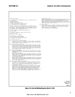
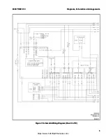
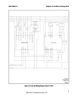
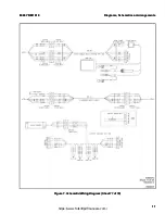
Page 5: ...Sheet 1 of 18 Figure 1 Schematic Wiring Diagram Sheet 1 of 18 8 80 00 00 0 Y YR RM M 1 16 61 19 9 D Di ia ag gr ra am ms s S Sc ch he em ma at ti ic cs s o or r A Ar rr ra an ng ge em me en nt ts s 1...

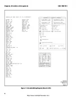
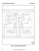
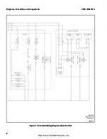
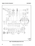
Page 6: ...Sheet 2 of 18 Figure 1 Schematic Wiring Diagram Sheet 2 of 18 D Di ia ag gr ra am ms s S Sc ch he em ma at ti ic cs s o or r A Ar rr ra an ng ge em me en nt ts s 8 80 00 00 0 Y YR RM M 1 16 61 19 9 2...

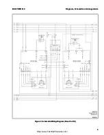
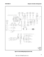
Page 7: ...Sheet 3 of 18 Figure 1 Schematic Wiring Diagram Sheet 3 of 18 8 80 00 00 0 Y YR RM M 1 16 61 19 9 D Di ia ag gr ra am ms s S Sc ch he em ma at ti ic cs s o or r A Ar rr ra an ng ge em me en nt ts s 3...

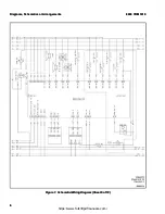
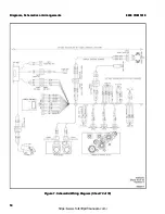
Page 8: ...Sheet 4 of 18 Figure 1 Schematic Wiring Diagram Sheet 4 of 18 D Di ia ag gr ra am ms s S Sc ch he em ma at ti ic cs s o or r A Ar rr ra an ng ge em me en nt ts s 8 80 00 00 0 Y YR RM M 1 16 61 19 9 4...

Page 9: ...Sheet 5 of 18 Figure 1 Schematic Wiring Diagram Sheet 5 of 18 8 80 00 00 0 Y YR RM M 1 16 61 19 9 D Di ia ag gr ra am ms s S Sc ch he em ma at ti ic cs s o or r A Ar rr ra an ng ge em me en nt ts s 5...

Page 10: ...Sheet 6 of 18 Figure 1 Schematic Wiring Diagram Sheet 6 of 18 D Di ia ag gr ra am ms s S Sc ch he em ma at ti ic cs s o or r A Ar rr ra an ng ge em me en nt ts s 8 80 00 00 0 Y YR RM M 1 16 61 19 9 6...

Page 11: ...Sheet 7 of 18 Figure 1 Schematic Wiring Diagram Sheet 7 of 18 8 80 00 00 0 Y YR RM M 1 16 61 19 9 D Di ia ag gr ra am ms s S Sc ch he em ma at ti ic cs s o or r A Ar rr ra an ng ge em me en nt ts s 7...

Page 12: ...Sheet 8 of 18 Figure 1 Schematic Wiring Diagram Sheet 8 of 18 D Di ia ag gr ra am ms s S Sc ch he em ma at ti ic cs s o or r A Ar rr ra an ng ge em me en nt ts s 8 80 00 00 0 Y YR RM M 1 16 61 19 9 8...

Page 13: ...Sheet 9 of 18 Figure 1 Schematic Wiring Diagram Sheet 9 of 18 8 80 00 00 0 Y YR RM M 1 16 61 19 9 D Di ia ag gr ra am ms s S Sc ch he em ma at ti ic cs s o or r A Ar rr ra an ng ge em me en nt ts s 9...

Page 14: ...eet 10 of 18 Figure 1 Schematic Wiring Diagram Sheet 10 of 18 D Di ia ag gr ra am ms s S Sc ch he em ma at ti ic cs s o or r A Ar rr ra an ng ge em me en nt ts s 8 80 00 00 0 Y YR RM M 1 16 61 19 9 10...

Page 15: ...eet 11 of 18 Figure 1 Schematic Wiring Diagram Sheet 11 of 18 8 80 00 00 0 Y YR RM M 1 16 61 19 9 D Di ia ag gr ra am ms s S Sc ch he em ma at ti ic cs s o or r A Ar rr ra an ng ge em me en nt ts s 11...

Page 16: ...eet 12 of 18 Figure 1 Schematic Wiring Diagram Sheet 12 of 18 D Di ia ag gr ra am ms s S Sc ch he em ma at ti ic cs s o or r A Ar rr ra an ng ge em me en nt ts s 8 80 00 00 0 Y YR RM M 1 16 61 19 9 12...

Page 17: ...eet 13 of 18 Figure 1 Schematic Wiring Diagram Sheet 13 of 18 8 80 00 00 0 Y YR RM M 1 16 61 19 9 D Di ia ag gr ra am ms s S Sc ch he em ma at ti ic cs s o or r A Ar rr ra an ng ge em me en nt ts s 13...

Page 18: ...eet 14 of 18 Figure 1 Schematic Wiring Diagram Sheet 14 of 18 D Di ia ag gr ra am ms s S Sc ch he em ma at ti ic cs s o or r A Ar rr ra an ng ge em me en nt ts s 8 80 00 00 0 Y YR RM M 1 16 61 19 9 14...

Page 19: ...eet 15 of 18 Figure 1 Schematic Wiring Diagram Sheet 15 of 18 8 80 00 00 0 Y YR RM M 1 16 61 19 9 D Di ia ag gr ra am ms s S Sc ch he em ma at ti ic cs s o or r A Ar rr ra an ng ge em me en nt ts s 15...

Page 20: ...eet 16 of 18 Figure 1 Schematic Wiring Diagram Sheet 16 of 18 D Di ia ag gr ra am ms s S Sc ch he em ma at ti ic cs s o or r A Ar rr ra an ng ge em me en nt ts s 8 80 00 00 0 Y YR RM M 1 16 61 19 9 16...

Page 21: ...eet 17 of 18 Figure 1 Schematic Wiring Diagram Sheet 17 of 18 8 80 00 00 0 Y YR RM M 1 16 61 19 9 D Di ia ag gr ra am ms s S Sc ch he em ma at ti ic cs s o or r A Ar rr ra an ng ge em me en nt ts s 17...

Page 22: ...eet 18 of 18 Figure 1 Schematic Wiring Diagram Sheet 18 of 18 D Di ia ag gr ra am ms s S Sc ch he em ma at ti ic cs s o or r A Ar rr ra an ng ge em me en nt ts s 8 80 00 00 0 Y YR RM M 1 16 61 19 9 18...

Page 23: ...Sheet 1 Figure 2 Hydraulic Schematic for NR045EB NDR035EB NR035EB NR040EB and NDR030EB Sheet 1 of of 2 2 8 80 00 00 0 Y YR RM M 1 16 61 19 9 D Di ia ag gr ra am ms s S Sc ch he em ma at ti ic cs s o o...

Page 24: ...Sheet 2 Figure 2 Hydraulic Schematic for NR045EB NDR035EB NR035EB NR040EB and NDR030EB Sheet 2 of of 2 2 D Di ia ag gr ra am ms s S Sc ch he em ma at ti ic cs s o or r A Ar rr ra an ng ge em me en nt...

Page 25: ...0DB NDR030DB Figure 3 Hydraulic Schematic for NR035DB NR040DB NDR030DB 8 80 00 00 0 Y YR RM M 1 16 61 19 9 D Di ia ag gr ra am ms s S Sc ch he em ma at ti ic cs s o or r A Ar rr ra an ng ge em me en n...

Page 26: ...NOTES NOTES 22 22 https www forkliftpdfmanuals com...

Page 27: ...https www forkliftpdfmanuals com...

Page 28: ...https www forkliftpdfmanuals com...

Reviews: