


600 YRM 496
Cylinder Head, Camshaft, and Valve Mechanism Repair
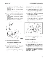
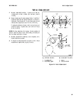
10. Align timing marks for crankshaft pulley. See Fig-
ure 23. Install crankshaft pulley, tapered ring, and
capscrew. Tighten capscrew to 160 to 170 N•m
(118 to 125 lbf ft).
1.
CRANKSHAFT
PULLEY
2.
TIMING MARK
Figure 23. Timing Belt Installation
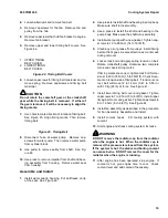
11. Install timing belt tensioner and spring. Move ten-
sioner fully toward intake side of engine and tem-
porarily tighten lock bolt.
12. Clean any oil or grease from pulleys. Install timing
belt so that it goes in same direction as mark made
during removal.
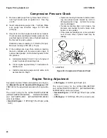
13. Loosen lock bolt and apply spring tension on belt.
Rotate crankshaft pulley clockwise two complete
turns and check timing marks.
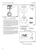
If timing marks are correct, tighten lock bolt for ten-
sioner to 20 to 35 N•m (15 to 26 lbf ft). Check move-
ment on tension side of timing belt. If tension is cor-
rect, belt will move 12 to 14 mm (0.47 to 0.55 in.)
with 10 kg (20 lb) of force. See Figure 24.
14. Install lower timing belt cover and gasket. Tighten
capscrews to 7 to 8 N•m (5 to 6 lbf ft). Install upper
timing belt cover and gasket. Tighten capscrews to
8 to 12 N•m (6 to 9 lbf ft). See Figure 25.
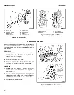
15. Install distributor. See Distributor Repair for proce-
dures.
1.
TENSIONER
2.
SPRING
3.
LOCK BOLT
4.
TENSION SIDE
Figure 24. Timing Belt Installation
1.
LOWER TIMING BELT COVER
2.
UPPER TIMING BELT COVER
Figure 25. Timing Belt Covers
9
Summary of Contents for GDP16-20AF
Page 37: ......


