in increments of 1%. A 100% setting provides maximum regenerative braking while a 0% setting in effect
deactivates regenerative braking.
The Auto Deceleration Rate setting is the second setting down from the top. The setting value can be in the 0
to 100% in increments of 1%. A 100% setting provides maximum auto deceleration while a 0% setting in
effect deactivates it. Auto Deceleration rate is always a percentage of the current Regenerative Braking Rate.
Thus, if Regeneration brake = 0% then Auto Deceleration = 0%.
The Auto Deceleration Type is the third setting down from the top. To change the type, use the
2
and
3
soft
keys to select the current type and press the
Enter Key
. Next, use the
2
or
3
soft key to choose either Pedal
Up or Proportional deceleration and press the
Enter Key
to save the new setting. Pedal Up deceleration
allows the truck to coast until the pedal is fully released. Proportional deceleration causes the truck to
decelerate in proportion to how far the pedal is released in relation to the current traction speed. A fully
released pedal produces maximum deceleration for both Pedal Up or Proportional deceleration.
STEERING WHEEL FRICTION AND STEERING TURNS ADJUSTMENT
NOTE:
This submenu is available to logged in Service Technicians and Supervisors.
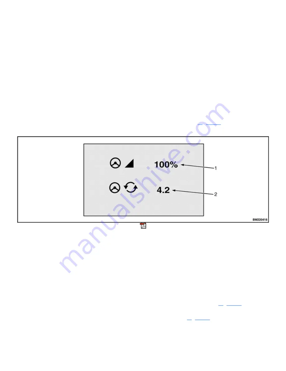
On trucks equipped with electronic steering or "E-Steer", the screen shown in
allows the operator to
adjust the friction on the steering wheel and the number of steering wheel turns from stop to stop.
1.
STEERING WHEEL FRICTION SETTING IN %
2.
STEERING WHEEL NUMBER OF TURNS LOCK TO LOCK
Figure 65. Steering Wheel Friction and Steering Turns
How to Adjust Settings
Steering Friction Setting
1.
Open the "Steering Wheel Friction and Steering Turns Adjustment" screen. See
.
2.
Navigate cursor to the steering friction setting and press enter. See
Summary of Contents for ERC40VH
Page 8: ...Figure 3 Supervisor Flowchart Sheet 1 of 4...
Page 9: ...Figure 3 Supervisor Flowchart Sheet 2 of 4...
Page 10: ...Figure 3 Supervisor Flowchart Sheet 3 of 4...
Page 11: ...Figure 3 Supervisor Flowchart Sheet 4 of 4 Table 1 Supervisor Menu Flowchart A B C D E F G H...
Page 21: ...Hydraulics Icon Alert Screens Cycle the Key Secure Battery Release Park Brake...
Page 22: ...Operator Out of Seat Release Pedal Release Hydraulic Input Traction Switch...
Page 23: ...Hydraulic Switch Temperature Too High Lift Limit Charge Battery...
Page 26: ...Display Title Screen Status Title Screen Truck Setup Title Screen...
Page 105: ...Figure 71 Steering Wheel Number of Turns Valid Entry...


