Yale CPE Operating And Maintenance Manual Download Page 6

Yale Electric Chain Hoist CPE

Yale

electric

6

Assembly of the trolley

 (see Fig. 12)

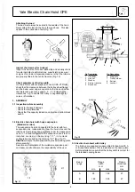
1.) Unscrew the locking nuts (item 9) and hex. nuts (item 2)

from the crossbars (item 1) and remove both side plates

(item 6) from the trolley.

2.) Measure the flange width of the beam (see Fig. 1 1 -

measurement "b").

3.) Adjust measurement "B" between the shoulders of the

round nuts (item 5) on the threaded crossbars (item 1).

Ensure that the 4 bores in the round nuts face towards the

outside. Adjust the measurement "B" to equal measure-

ment "b" plus 4 mm. Measurement "A" must be 2 mm on

either side and the suspension traverse (item 4) must be

centred between the round nuts.

4.) Replace one side plate (item 6):
Replace one side plate ensuring that the roll pins (item 8)

engage into one of the bores in the round nuts.  To achieve

this it may be necessary to rotate the round nuts slightly .

5.) Replace the washers (item 3) and tighten the hex. nuts

(item 2). Screw on the locknuts (item 9) fingertight and

tighten a further 1/4 to 1/2 turn.

Attention:

 The locknuts must always be fitted.

6.) Loosely replace the second side plate (item 6) on the

crossbars (item 1). The washers (item 3), hex. nuts (item2)

and locknuts (item 9) can be fitted loosely .

7.) Raise the complete pre-assembled trolley to the carrying

beam.

8.) Engage the second side plate (item 6) ensuring that the

roll pins (item 8) engage into one of the bores in the round

nuts (item 5). To achieve this it may be necessary to rotate

the round nuts slightly .

9.) Tighten the hex. nuts (item 2) on the second side plate.

Tighten the locknuts (item 9) fingertight and then a further

1/4 to 1/2 turn.

Attention:

 The locknuts must always be fitted.

10.) By traversing the trolley check the following:
• that a clearance of 2 mm is maintained on each side

between the trolley wheel flanges and the beam outer edge.
• that the suspension traverse is centred below the beam.
• that all 4 locknuts (item 9) are fitted.

11.) Model CPE-VTG only:

To fit the hand chain position the slot on the outer edge of

the hand chain wheel below the chain guide. Place any

one link of the endless hand chain vertically into the slot

and turn the hand chain wheel until the link  has passed

the chain guides on both sides.

Attention:

 Do not twist the hand chain when fitting.

Geared trolleys are moved by pulling the hand chain.

3.4 Electrical connection

Attention

Work at electrical installations may be carried out by

electrical experts only. The local regulations have to be

strictly observed, in Germany DIN 7100 / VDE 0100 and

DIN 57113 / VDE 0113.

Preparation

• Before beginning work on electrical components the

mains current switch must be switched OFF and secured

against unintentionally being switched back on.

• Before connecting the chain hoist ensure that  the

electrical data on the nameplate match the local supply

specifications.

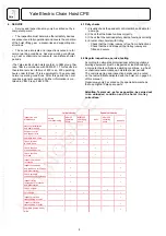
• The mains supply cable must be an insulated cable with

4 flexible leads. The ground (earth) lead must be longer

than the live leads. For wire cross-section and fusing see

table on page 7.

• The length of the pendant control cable is determined by

working conditions. Attach the tension relief wire in a manner

that the pendant control cable hangs load-free.

• Wiring and terminal connecting diagrams are included

with the hoist.

Mains supply connection

1.) The mains supply cable must be connected to the

electric chain hoist before it is connected to the mains

supply.

2.) On chain hoists with an electric trolley (CPE-VTE) the

three phases of the mains supply are to be connected to

the terminal strip within the terminal box on the trolley. The

ground/earth wire is to be connected to the special ground/

earth connection within the terminal box of the chain hoist.

3.) On chain hoists without electric trolley the mains supply

and the ground/earth wire are to be connected to the

terminal strip within the terminal box of the chain hoist.

4.) After removing the terminal box cover, connect the wiring

as shown on the wiring diagram label inside the terminal

box cover.

Attention:

  On hoists with direct control the ground/earth

wire should always be connected according to the wiring

diagram. Should the mains supply source not provide a

ground (earth) connection please consult the manufacturer.

5.) After replacing the terminal box cover, connect the other

end of the supply cable to the mains supply .

6.) Check the motor's direction of rotation.

The wiring diagram included has been drawn for a normal,

clockwise rotating installation.Should the user's mains

supply not fulfil these requirements, e.g. the hoist lowers

when lift is selected (or vice versa) switch the unit OFF

immediately and exchange two of the three phase

connections in the mains connection.

Attention:

Under no circumstances may the wiring in the pendant

control be tampered with.

Summary of Contents for CPE

Page 1: ...g Electric Chain Hoist Series CPE Mod CPE F Capacity 1600 kg 5000 kg Yale electric Yale Industrial Products GmbH P O Box 10 13 24 D 42513 Velbert Germany Am Lindenkamp 31 D 42549 Velbert Germany Tel 20 51 600 0 Fax 20 51 600 127 Ident No 09900069 10 02 ...

Page 2: ... 0 52 5 5 1 25 1 Am 98 180 or 180 300 1800 11 11 2 8 0 37 0 3 0 09 40 40 20 CPE 30 5 CPEF 30 5 3000 1 25 25 15 2 8 2 8 0 7 5 5 1 25 1 Bm 98 180 or 180 300 1800 11 11 2 8 0 37 0 3 0 09 40 40 20 CPE 32 4 CPEF 32 4 3200 2 40 40 20 2 3 2 3 0 52 4 4 1 1 Am 98 180 or 180 300 1800 11 11 2 8 0 37 0 3 0 09 40 40 20 CPE 40 4 CPEF 40 4 4000 2 25 25 15 2 8 2 8 0 7 4 4 1 1 Bm 98 180 or 180 300 1800 11 11 2 8 0...

Page 3: ...ransport loads while personnel are in the danger zone Do not allow personnel to pass under a suspended load see Fig 2 After lifting or tensioning a load must not be left unattended for a longer period of time Start moving the load only after it has been attached correctly and all personnel are clear of the danger zone Attaching the hoist trolley The operator must ensure that the hoist trolley is a...

Page 4: ...t use the chain end stop as an operational limit device see Fig 1 chain end stop Do not throw the hoist hoist or trolley down Always place it properly on the ground 2 3 Initial operation Inspection before initial operation Each hoist trolley must be inspected prior to initial operation by a competent person and any failures be removed The inspection is visual and functional and shall establish tha...

Page 5: ...hook CPE VTP G E check that the clearance between the trolley wheel flange and the beam outer edge is equal on both sides and within the tolerances given see page 6 2 3 Enlarging the clearances e g to enable the trolley to negotiate tighter curves is forbidden 3 ASSEMBLY 3 1 Inspection before assembly Check for transport damage Check for completeness Check that the capacity indication on hoist and...

Page 6: ...e hand chain 3 4 Electrical connection Attention Work at electrical installations may be carried out by electrical experts only The local regulations have to be strictly observed in Germany DIN 7100 VDE 0100 and DIN 57113 VDE 01 13 Preparation Before beginning work on electrical components the mains current switch must be switched OFF and secured against unintentionally being switched back on Befo...

Page 7: ...hen it is not under load see page 8 Before the hoist is put into regular service following additional inspections must be made Are all screwed connections on hoist and trolley tight and are all locking devices in place and secure Are the end stops on the trolley runway in place and secure Is the chain drive correctly reeved Is the chain end stop correctly fitted to the loose end of the load chain ...

Page 8: ...tate shorter periods The Yale electric chain hoists conform to FEM group 1Am resp 1Bm in accordance with FEM 9 511 This results in a theoretical service lifetime of 800 resp 400 operating hours under full load This is equivalent to 10 years under normal operating conditions After this period the hoist requires a general overhaul Further information is con tained in VBG 9 resp FEM 9 755 6 1 Daily c...

Page 9: ...ards the chain guide and away from the load sheave Operate the hoist in the lowering direction to feed the chain through the hoist 4 Fitting lower block and chain end stop Slide the end buffers over the loose ends of the load chain and refit bottom block and chain end stop The chain end stop must be fitted so that at least 1 link remains free see Fig 1 5 Before initial operation lubricate the unlo...

Page 10: ...d Check for cracks or wear Suspension pins Connection between hoist and suspension hook resp trolley Check for cracks or wear Ensure all safety devices are in place and secure 6 7Overload protection device The overload protection device slipping clutch is factory set to 1 10 10 of the rated capacity and can be checked by lifting a suitable load If the device slips at the rated capacity load it can...

Page 11: ...xact adjustment of the overload device is only possible when the hoist is completely reassembled Pre adjustment of the cup spring 41 is made with the fixing screw 42 After the exact adjustment has been made the fixing screw 42 is secured by means of the ball 46 and the threaded pin 47 6 9 MOTOR Motor Under normal conditions the motor is practically main tenance free Every 2 1 2 years the bearings ...

Page 12: ...Yale Electric Chain Hoist CPE Yale electric 12 1 2 6 4 7 8 9 11 11 15 19 20 5 7 Fig 16 Hoist body 3 10 18 22 17 14 16 13 23 29 12 14 14 14 25 26 ...

Page 13: ...116 2 speeds 1 0600117 0600117 0600117 0600117 0600117 0600117 0600117 13 Planetary gear 1 0609678 0609678 0608814 0608814 0609678 0609678 0608814 14 Hex screw 8 9101660 9101660 9101660 9101660 9101660 9101660 9101660 15 Suspension bolt 2 0609388 0609388 0609388 0609388 0609388 0609388 0609388 16 Bolt locking device 1 0609448 0609448 0609448 0609448 0609448 0609448 0609448 17 Cyl screw 2 9102150 9...

Page 14: ...ing 1 9139020 8 Chain bolt 1 0608855 9 Buffer 1 0609734 10 14 Chain end stop assy 1 0609995 10 Chain end stop half 2 0608867 11 Cyl screw 1 9102019 12 Lockwasher 1 9122032 13 Hex nut 1 9115014 14 Buffer 1 0609734 CPE F 32 Item Description Qty CPE F 40 No CPE F 50 15 23 Bottom block assy 3200 kg 1 0609681 Bottom block assy 4000 kg 1 0609994 Bottom block assy 5000 kg 1 0609510 15 Swivel half 2 06094...

Page 15: ...15 2 3 1 Fig 18 Chain Container Item Description Qty Yale Part No No all models 1 Chain container assy for 13 m linear chain length 1 6109467 1 Chain container assy for 21 m linear chain length 1 6109468 2 Cyl screw 1 9102255 3 Hex nut 1 9115098 ...

Page 16: ...ctric 16 Fig 19 Gearbox Prior to assembl y soak in oil for 1 hour Fitted with Loctite 243 5900 6000 N Pre tension of cup spring Secu re with Loct ite 243 afte r com pleti on of clutc h adju stme nt 0 3 kg Tran smis sion oil Fina Gera n L460 ...

Page 17: ...ys indicate serial number and mfg year of hoist Item Description Qty Model No CPE 30 5 Planet gearbox assy 1 0600230 1 Gearbox housing 1 0600237 2 Ring 1 0600238 3 Planet gear carrier 1 0600239 4 Packing ring 1 9172110 5 Bearing 1 9150043 6 Stop washer 6 9153043 7 Planet gear 3 0600240 8 Needle bearing 6 9153090 9 Spacer ring 3 0600241 10 Planet gear shaft 3 0600242 11 Snap ring 1 9129070 13 Ring ...

Page 18: ...188 0600188 7 Fan cover 1 0600189 0600189 8 Terminal box assy 1 0600190 0600190 board box box cover box seal 9 Rectifier 1 0600110 0600110 16 Armature disc 1 0600113 0600113 17 Brake fan 1 0600112 0600112 18 Fitting parts set for mounting 1 0600194 0600194 the brake brake spring O ring cap screw washers fitting key 19 Manual brake release system optional 1 0600195 0600195 Attention When ordering s...

Page 19: ...e tag L2 1 0609818 Name tag L3 1 0609819 Name tag PE 1 0609820 Name tag 3 0609821 Name tagF5 1 0609822 Name tag F6 1 0609823 Item Description Qty Yale Part No No all models 15 Screw fitting 3 9184082 16 Screw fitting 1 9184081 17 Counter nut 1 9184085 18 Counter nut 3 9184086 19 Plate 1 0609788 20 Screw 2 9103013 21 Washer 2 9121001 22 Cyl screw 4 9107023 23 Connecting cable CPE only 1 0609828 Con...

Page 20: ...ssy with emergency stop 1 0609454 0609455 2 Control cable specify length 9062407 9062407 3 Wiring diagram 1 0609631 0609632 4 Clamp 2 0605355 0605355 5 Screw fitting 1 9184082 9184082 6 Screw fitting 1 9184084 9184084 7 Fastener 1 0608882 0608882 8 Hex screw 1 9101661 9101661 9 Washer 1 9121006 9121006 10 Strain relief specify length 9093001 9093001 10 ...

Page 21: ...0609687 2 Carrier for contact element 1 0609965 0609965 3 Lowering button DN 1 0609966 0609967 Lifting button UP 1 0609968 0609969 4 Contact element emerg stop 1 0609978 0609978 5 Emergency stop button 1 0609977 0609977 6 Rubber bushing 1 0609970 0609970 7 Loop for tension re lief device 1 0609971 0609971 8 Clamping piece 1 0609972 0609972 9 Interlocking lever 1 0609973 0609973 10 Front housing 1 ...

Page 22: ...m Description Qty CPE CPEF No 1 speed 2 speed Pendant control assy with emergency stop 1 0609566 0609567 1 Contact element 1 0609980 0609981 2 Emergency stop button 1 0609984 0609984 3 Lowering button DN 1 0609985 0609986 Lifting button UP 1 0609987 0609988 4 Contact element emerg stop 1 0609982 0609983 ...

Page 23: ...9170 5 Round nut 4 0559168 6 Washer 4 9121213 7 Hex nut 4 9115156 2 5 8 6 8 6 8 8 6 1 9 5 15 15 13 6 11 9 5 4 4 5 11 10 3 9 7 10 7 12 7 14 Fig 26 Plain Trolley 9 10 7 10 11 Item Description Qty Yale Part No No all models 8 Locking nut 4 9115155 9 Trolley wheel 4 0508210 10 Ball bearing 8 9151079 11 Snap ring 4 9129003 12 Identity plate 1 0559869 13 Grooved nail 4 9128004 14 Centre traverse 1 05593...

Page 24: ... 9151079 3 Snap ring 4 9129003 4 Support 1 0508229 5 Spacer tube 1 0719111 6 Lockwasher 4 9122016 7 Hex screw 2 9101050 8 Bushing 1 0102503 9 Spacer 4 9121205 Item Description Qty Yale Part No No all models 10 Hand chain guide 1 0558062 11 Hex screw 2 9101014 12 Hex nut 2 9115148 13 Drive shaft 1 0719671 14 Roll pin 1 9134052 15 Hand chain wheel 1 0558061 16 Hand chain specify length 4307654 17 Co...

Page 25: ...5 Flange 1 0719371 6 Drive shaft 1 0719372 7 Fitting key 1 9131072 8 Needle bearing 1 9153077 9 Snap ring 1 9129016 10 Hex screw 4 9101170 11 Lockwasher 4 9122003 12 Roll pin 1 9134080 Item Description Qty Yale Part No No all models 13 Hex nut 2 9101014 14 Lockwasher 2 9122004 15 Spacer 7 9121215 16 Pinion 1 0719373 17 Snap ring 1 9123038 18 Screw fitting 1 9184082 19 Brake motor 1 speed 1 0609586...

Page 26: ...3 0600030 0600030 0600023 0600023 0600030 0600030 0600023 4 button UP hoist 1 0600024 0600031 0600031 0600024 0600024 0600031 0600031 0600024 5 button LEFT trolley 1 0600023 0600030 0600023 0600030 0600023 0600030 0600023 0600030 6 button RIGHT trolley 1 0600024 0600031 0600024 0600031 0600024 0600031 0600024 0600031 7 Contact element em stop 1 2 0609978 0600032 8 10 Housing assy without contacts ...

Page 27: ... 12 1 3 31 6 Zuleitung Cable conductor hoist Fig 30 Contactor control CPE F with VTE F 7 14 17 10 2 6 6 29 30 16 9 15 16 20 23 22 18 8 32 Item Description Qty Yale Part No No all models Name tag 3 0609821 Name tagF5 1 0609822 Name tagF6 1 0609823 18 Wiring diagram CPE VTE 1 0609854 Wiring diagram CPEF VTE 1 0609856 Wiring diagram CPE VTEF 1 0609855 Wiring diagram CPEF VTEF 1 0609853 19 Identity pl...

Page 28: ...7 19 Fig 31 Direct control CPE F with VTE F 1 15 18 Cable conductor trolley Cable conductor hoist Zuleitung Item Description Qty Yale Part No No all models 15 Wiring diagram CPE VTE 1 0609882 Wiring diagram CPEF VTE 1 0609883 Wiring diagram CPE VTEF 1 0609884 Wiring diagram CPEF VTEF 1 0609885 15 Name plate 1 0719680 17 Control switch CPE VTE 1 0609610 Control switch CPEF VTE 1 0609832 Control swi...

Page 29: ...Yale Electric Chain Hoist CPE electric Yale 29 ...

Page 30: ...Yale Electric Chain Hoist CPE Yale electric 30 InspectionChart Inspectionbeforeinitialoperation by Date of initial operation RegularInspections Date Findings Repair Test Date by competent person ...

Page 31: ...st Serial number from manufacturing year 1 95 Serial numbers for the individual capacities models are registered in the production book with the remark CE sign Relevant EC Directives EC Machinery Directive 98 37 EEC Transposed harmonised standards in particular EN 292 part 1 safety of machines EN 292 part 2 safety of machines EN 349 safety of machines EN 818 part 1 round link chain EN 818 part 4 r...

Page 32: ...Yale Electric Chain Hoist CPE Yale electric 32 Quality engineered and performance tested recognisably ...

Reviews: