TOOLS REQUIRED: Screwdriver, 11/32 wrench, socket or nut driver, a 7/16" wrench and 1/2"
wrench and socket, tape measure.
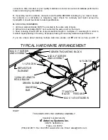
1. Layout the boom sections as shown on Dimension Sheet and assemble using (6) 8-32 x 1-3/4"
screws, locknuts. Tighten the nuts securely.
2. Use the Dimension Sheet as reference for installing the ELEMENT HALVES on to the ELEMENT
MOUNTING BLOCKS. For each element insert a 1/4 x 10” Element Support Rod from the drilled end.
Secure the rod / element assemblies to the element mounting blocks with (10) 8-32 x 1" screws and
locknuts. Install screws from bottom of blocks.
3. Mount the longest element (REFLECTOR) to the hole at the rear end of the boom using a 8-32 x
2" screw and locknut. Tighten securely.
4. Mount the DRIVEN ELEMENT next, threading the 8-32 x 2” screw into the 'T' MATCH BLOCK held
to the underside of the boom. Orient the match block with the “N” feed connector pointed to the front.
Mount the remaining DIRECTOR ELEMENTS. Carefully note lengths on Dimension Sheet:.
5. Thread the gold SEAL NUTS all the way onto the two small connectors on the 'T' match block
with
the black neoprene side out.
Then connect the balun connectors and tighten them
GENTLY
with a
7/16" end wrench. Now run the seal nuts up against the face of the balun connectors and tighten
them about 1/2 turn with a 1/2" end wrench. Secure coiled balun to boom with two nylon ties. The
balun does not need to be coiled. It can be unrolled and fastened to the boom to the front or rear.
6. Install two 8-32 x 1/4” Set screws into each SHORTING BAR. Then slide a SHORTING BAR onto
each DRIVEN ELEMENT HALF and position per the DIMENSION SHEET. Align rods and element
halves parallel and tighten the set screws with the 5/64" Allen wrench provided.
7. Install the feedline or a short section long enough to reach the boom center and on down the mast
and on past the the top of the tower. If the short section is used then the main feedline can be
attached at the time of installation on the tower. Tightening the Male 'N' connector carefully, and route
the cable forward on the boom, securing it with the cable ties provided. Stop about 24" in front of the
first director.
8. Mount the BOOM TO MAST PLATE perpendicular to elements at or near the physical balance
point of the antenna. Secure with the 1-1/2" U-bolts, 5/16” stainless steel lockwashers and nuts. Do
not over-tighten as severe boom distortion and subsequent weakening can occur. 2” U-bolts are
supplied for attaching the plate to your mast.
9. When the antenna is installed in position on the mast, the main feedline can be connected and
sealed at that time. REMEMBER to support the feedline at the antenna boom and on the mast.
Leave an adequate feedline loop for rotation around the tower. When stacking this antenna with other
HF models, maintain a minimum 5’ of separation; more if practical. Mount horizontally polarized VHF
and UHF antennas at least 40” above or below this antenna to minimize interaction.
10.
INSTALLATION AND STACKING INFORMATION
A
. A mast or cross boom that supports the antenna
in the element plane
must be non
conductive (fiberglass, etc). The feed line must also always exit the antenna at 90 degrees or
perpendicular to the elements for at least 60 inches.
B
. To protect your investment in this high performance antenna, always use high quality coax and


