background image

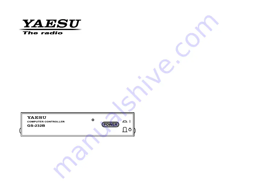
GS-232B

Computer Control Interface for

Antenna Rotators

YAESU MUSEN CO., LTD.

Tennozu Parkside Building

2-5-8 Higashi-Shinagawa, Shinagawa-ku, Tokyo 140-0002 Japan

YAESU USA

6125 Phyllis Drive, Cypress, CA 90630, U.S.A.

YAESU UK

Unit 12, Sun Valley Business Park, Winnall Close

Winchester, Hampshire, SO23 0LB, U.K.

Summary of Contents for GS-232B

Page 1: ...ators YAESU MUSEN CO LTD Tennozu Parkside Building 2 5 8 Higashi Shinagawa Shinagawa ku Tokyo 140 0002 Japan YAESU USA 6125 Phyllis Drive Cypress CA 90630 U S A YAESU UK Unit 12 Sun Valley Business Pa...

Page 2: ......

Page 3: ...ically to support it software is not supplied by Yaesu In addition to reading and setting antenna angle and ro tation speed the firmware includes clocked positioning G eneral D escription routines to...

Page 4: ...On The Equipment ON power Stand by Direct current S pecifications Connector Pinouts Serial I O 9 pin DB 9 connector RS 232C connector Pin 2 Tx Data Pin 3 Rx Data Pin 5 Signal Ground Pin 7 RTS Pin 8 C...

Page 5: ...ug 1 pc Hook loop fasteners for mounting 1 pc 1 G 800DXA G 1000DXA G 2800DXA G 800DXC G 1000DXC and G 2800DXC 2 G 5400B G 5600B and G 5500 A ccessories O ptions Available Options C 1000 Connection Cab...

Page 6: ...source of 12 VDC The red lead connects to the Positive DC terminal and the black lead connects to the Negative DC terminal The GS 232B requires 70 mA The supplied cable has a 500 mA fast blow fuse Us...

Page 7: ...anel of the GS 232B Figure 2 G 400 G 500 or G 400 G 550 pair of GX 500 Connect the supplied DC cable to a source of 12 VDC The red lead connects to the Positive DC terminal and the black lead connects...

Page 8: ...B Figure 4 Replace the Top Cover Connect the supplied DC cable to a source of 12 VDC The red lead connects to the Positive DC terminal and the black lead connects to the Negative DC terminal The GS 23...

Page 9: ...on Within 15 seconds of swithing the GS 232B s power press the Enter key several times to adjust the GS 232B s data baud rate to the Computer s data baud rate If the computer is successul to setting t...

Page 10: ...r s dis play should show AZ aaa where aaa is a three digit number which indicates the azimuth heading in degrees Adjust the OUT VOL ADJ potentiometer on Control ler rear panel so as to get a reading o...

Page 11: ...From the Controller panel set the Rotator fully clock wise to the right Press F F and Enter on the computer keyboard to activate the Control Interface s azimuth A D converter calibration routine The c...

Page 12: ...ntroller panel set the Azimuth Rotator fully clockwise to the right Press F F and Enter on the computer keyboard to activate the Control Interface s azimuth A D converter calibration routine The compu...

Page 13: ...or to full scale 180 right horizon Press F2 F 2 and Enter on the computer keyboard to activate the Control Interface s elevation A D converter calibration routine The computer will display AZ aaa EL e...

Page 14: ...of 450 on the computer s display This reading 450 360 degrees 90 degrees cor responds to the actual beam heading you established when you pointed the azimuth rotator fully clockwise Press Enter on the...

Page 15: ...and Enter on the computer keyboard to activate the Control Interface s elevation A D converter calibration routine The computer will display AZ aaa EL eee where eee is a three digit number which indi...

Page 16: ...ress F2 F 2 and Enter on the computer keyboard to activate the Control Interface s elevation A D converter calibration routine The computer will display AZ aaa EL eee where eee is a three digit number...

Page 17: ...Keep in mind that all commands require that the Enter key be pressed after the command letter or 0Dh be sent by a control program although we will not repeat this when discussing the commands Also not...

Page 18: ...scale send command adjust OUT VOL ADJ trimmer on rear of controller or GX 500 elevation adapter until the returned data is 180 or 450 0nn 180 for elevation Press Enter on the computer keyboard to exi...

Page 19: ...m eters are present the first one is interpreted by the Control Interface as the rotation interval sss not an angle Valid ranges are 001 to 999 for sss and 000 to 360 or 450 depending on rotator type...

Page 20: ...lways be supplied when chang ing elevation and that a setting point consists of a pair of angles Waaa eee Turn to aaa degrees azimuth and eee degrees elevation where aaa is a three digit number betwee...

Page 21: ...kwise Rotation L Counter Clockwise Rotation A CW CCW Rotation Stop C Antenna Direction Value M Antenna Direction Setting MXXX M Time Interval Direction Setting MTTT XXX XXX XXX TTT Step value XXX Hori...

Page 22: ...ibration F2 Full Scale Calibration B Elevation Antenna Direction Value Command List Returned by H3 Command HELP COMMAND 3 P45 Set_mode 450 Degree P36 Set_mode 360 Degree Z Swicth N Center S Center MOD...

Page 23: ...Shinagawa ku Tokyo 140 0002 Japan Applicable Standards This equipment is tested to and conforms to the essential requirements of directive as included in following standards SAFETY 1999 5 EC Art 3 1 a...

Page 24: ...Copyright 2016 YAESU MUSEN CO LTD All rights reserved No portion of this manual may be reproduced without the permission of YAESU MUSEN CO LTD 1606S DO Printed in Japan...

Reviews: