background image

2

Before Using

Introduction

Features of this radio

 144/430 MHz dual band mobile radio equipped with standard C4FM digital 

communication modem

 Clear audio and data communication is achieved using the digital modem functions

 Wide band receive in the 108 MHz to 999 MHz range (wireless business, public service 

and air band)

 Transmit power 50 watts with cooling fan

 Full color 3.5-inch LCD, high luminance TFT touch panel controller

 Intuitive, user touch panel operation

 500 memory channels in the Band A (band at the top of the display) and 500 channels 

in the Band B (band at the bottom of the display)

 The frequency and settings memories can be saved, using a micro-SD card. The data 

in the micro-SD card can easily be copied to other radios

 Diverse range of scanning functions (VFO scan, memory scan etc.)

 Built-in GPS receiver unit, location and movement information can be displayed and 

GPS data can be output to connected devices

 Incorporated  APRS

®

 functions. Position, movement data and messages can be 

communicated to other stations, digipeaters and the Internet.

  *Refer to the separate “APRS Operating Manual”

 GM (Group Monitor) function where in a group of frequently communicating members 

can be registered, and then position information and messages can be exchanged 
  

*Refer to the separate “GM Operating Manual”

 Supports Yaesu WIRES-X Internet linking, providing communication with remote 

partners using the Internet

  *Refer to the separate “WIRES-X Operating Manual”

 Bluetooth adaptor unit BU-2 (sold separately) permits hands-free operation

 Voice guide unit FVS-2 (sold separately) provides frequency voice announcement, and 

recording of received audio

 Camera-equipped microphone MH-85A11U (sold separately). Images taken with the 

camera can be transmitted to other stations, and also shown on the LCD display.

*  The APRS, GM and WIRES-X Operating Manuals are not included with the product. 

Please download them from the Yaesu website.

Application for FCC / IC 

FCC ID: K6620345X40 / IC: 511B-20345X40

Summary of Contents for FTM-400XDR

Page 1: ...tion Using the APRS Function Using the GM Function Convenient Functions Functions to be used when Necessary Customize Menu Settings and User Preferences Appendix 144 430MHz 50W DUAL BAND TRANSCEIVER C...

Page 2: ...data can be output to connected devices Incorporated APRS functions Position movement data and messages can be communicated to other stations digipeaters and the Internet Refer to the separate APRS Op...

Page 3: ...in such a way that it may interfere with the proper operation of the air bags After installing the radio check that the brake lamp head lamp turning indicator lights wiper etc are working normally wit...

Page 4: ...soft cloth and wring it out thoroughly before using it to wipe the touch panel When wiping the touch panel be careful not to wipe too hard or scratch the surface with your nails When the touch panel i...

Page 5: ...creen is to be touched quickly Touch SQL for 1 second or longer Indicates that the symbol on the touch panel screen is to be touched for one second or longer Select MODE Indicates that the items are t...

Page 6: ...modulation mode 46 Displaying the band scope 47 Muting the audio 48 Communicating 49 Transmitting 49 Adjusting the transmit power 50 Adjusting the sensitivity of the microphone 50 Communicating in th...

Page 7: ...ing the messages and pictures 123 Downloading messages and images 124 Sending messages and pictures 125 Creating and sending a message 125 Sending saved pictures 129 Replying to a message or picture 1...

Page 8: ...of the repeater 187 Setting the frequency step 188 Setting the volume of the beep 188 Setting the clock shift of the CPU 188 Setting the program key of the microphone 189 Expanding the receive range...

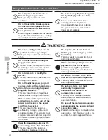
Page 9: ...le when these instructions are ignored and the product is handled wrongly Type and meaning of symbols Prohibited actions that must not be carried out in order to use this radio safely For example sign...

Page 10: ...leak electric shock and equipment failure When smoke or strange odors are emitted from the radio turn off the power and disconnect the power cord from the socket This may result in fire liquid leak ov...

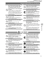
Page 11: ...oes off For safety reasons please pull the power plug of the DC power equipment connected to the product out of the AC socket Never touch the antenna as well This may result in fire electric shock and...

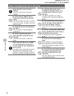
Page 12: ...om the electrical devices inverters etc fitted in the car Do not place the device on an unsteady or sloping surface or in a location where there is a lot of vibration The device may fall over or drop...

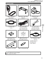
Page 13: ...rsion DC power cable with fuse attached European version Spare fuse 15 A USA EXP version Spare Fuse 15 A European version PC connection cable SCU 20 Operating Manual Warranty Card Quick Manual Microph...

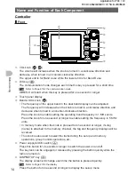
Page 14: ...r clockwise direction Press the knob to enable setting the operating band frequency in 1 MHz units Press the knob for one second or longer to enable setting the frequency in 5 MHz units In memory mode...

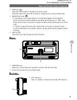
Page 15: ...the knob for one second or longer to enable setting the frequency in 5 MHz units In memory mode when the knob is pressed for one second or longer if a tag name is attached to the memory channel the ta...

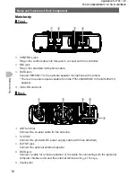
Page 16: ...put available from the FTM 400XDR DE to the MH 85A11U speaker micro SD card slot Back ANT terminal Connect the co axial cable for the antenna 13 8 VDC Connect the provided DC power supply cable with f...

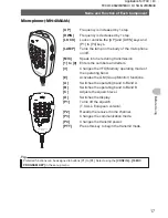
Page 17: ...numbers and letters Changes the VFO Memory operating mode of the operating band Activates the GM Group Monitor functions A Switches the operating band to Band A B Switches the operating band to Band...

Reviews: