19
Alignment
r
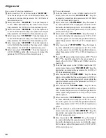
Select menu item “
42: VHF-MIN
.” Key the transmit-
ter, and confirm that the output power is 5 W (±1 W).
In case the power is not within the specified tolerance,
adjust this parameter for 5 W (±1 W) of transmission
power.
r
Tune the transceiver to the 430 MHz band in the CW
mode. Select the menu item “
43: UHF-MAX
.” Key the
transmitter, and adjust this parameter for 20 W (±1 W)
of transmission power.
r
Select menu item “
44: UHF-MID
.” Key the transmit-
ter, and confirm that the output power is 20 W (±0.3
W). In case the transmission power is not within the
specified tolerance, adjust this parameter for 20 W
(±0.3 W) of transmission power.
TX Gain Adjustment
r
Select the USB mode. Inject a 1 mV audio signal at a
frequency of 1 kHz from the AF generator into the
MIC
jack.
r
Tune the transceiver to the 1.8 MHz band and key the
transmitter. Select menu item “
45: HF1TXG
” and ad-
just this parameter for 70 W (±10 W) of transmission
power.
r
The other TX gain adjustment menus, “
46: HF2TXG
”,
“
47: HF3TXG
”, and “
48: 50MTXG
”, should be ad-
justed in the same manner as detailed above on the 7
MHz, 21 MHz, and 50 MHz bands, respectively.
r
Tune the transceiver to the 144 MHz band and key the
transmitter. Select menu item “
49: VHFTXG
” and ad-
just this parameter for 35 W (±5 W) of transmission
power.
r
Tune the transceiver to the 430 MHz band and key the
transmitter. Select menu item “
50: UHFTXG
” and ad-
just this parameter for 10 W (±2 W) of transmission
power.
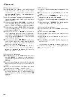
ALC Meter Adjustment
r
Tune the transceiver to the 21 MHz band in the USB
mode. Select menu item “
51: ALC-1
.” Key the trans-
ceiver without microphone input and press the [
A
] key.
Now, a value which the microprocessor computes will
be displayed on the LCD.
r
Rotate the main dial to adjust this parameter to a read-
ing four digits lower than the parame-ter value dis-
played in the previous step.
r
After setting the parameter, confirm that all the dots of
the ALC meter have gone out.
r
Select menu item “
52: ALC-M
.” Inject a 4.0mV AF
signal at 1 kHz audio frequency from an audio genera-
tor and key the transceiver.
r
Press the [
A
] key and confirm that 9 dots of the ALC
meter light up on the LCD.
Reverse ALC Adjustment
r
Set the mode on CW, and connect a 150-Ohm dummy
load to the antenna connector.
r
Key the transceiver on the 1.8 MHz band, and select
menu item “
53: HF1-RV
;” adjust this parameter for an
“S-8” S-meter reading on the LCD.
r
The other reverse ALC adjustment menus, “
54: HF2-
RV
”, “
55: HF3-RV
”, and “
56: 50M-RV
”, should be
adjusted in the same manner as shown above on the 7
MHz, 21 MHz, and 50 MHz bands, respectively.
r
Key the transceiver on the 144 MHz band and select
menu item “
57: VHF-RV
;” adjust this parameter for an
“S-6” S-meter reading on the LCD.
r
Key the transceiver on the 430 MHz band and select
menu item “
58: UHF-RV
;” adjust this parameter for an
“S-3” S-meter reading on the LCD.
Carrier Level Adjustment
r
Tune the transceiver to the 21 MHz band in the CW
mode. Connect a 50-Ohm dummy load to the antenna
connector. Select menu item “
59: CW-CAR
” and key
the transceiver.
r
Set this parameter such that the center of the meter on
the LCD lights up.
r
Connect the oscilloscope to the antenna connector via
an appropriate attenuator.
r
Set the mode to AM. Select menu item “
60: AM-CAR
.”
Inject a 1.5 mV audio signal at a frequency of 1 kHz
from the audio generator into the microphone jack.
r
Key the transceiver and adjust this parameter for 33%
AM modulation on the oscilloscope.
Summary of Contents for FT-897
Page 5: ...Block Diagram 5...
Page 6: ...Block Diagram 6 Note...
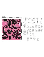
Page 21: ...21 MAIN Unit Circuit Diagram...
Page 22: ...22 MAIN Unit Note...
Page 52: ...52 MAIN Unit Note...
Page 59: ...59 PA Unit Circuit Diagram...
Page 60: ...60 PA Unit Note...
Page 73: ...73 PANEL Unit Circuit Diagram...
Page 74: ...74 PANEL Unit Note...
Page 75: ...75 PANEL Unit H Parts Layout Side A 1 2 3 F A C B E D BRPG1211C D4007 4010 4012 G...

