background image

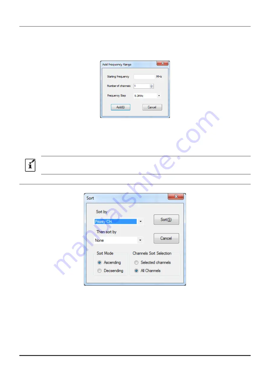
•  Add Frequency Range

New channels may be created in designated frequency steps from the starting frequency by clicking the 

left mouse button on the "Add Frequency Range" parameter in the "Edit" menu. The "Add Frequency 

Range" window will open.

A specified number of memory channels may be created, beginning from the starting frequency in the 

specified frequency steps.

Starting Frequency:  Enter the lower frequency

Number of Channel:  Enter the number of channels

Frequency Step:  

Enter the desire frequency step

Click the left mouse button on the [OK] button to create the additional specified memory channels.

* The 8.33 kHz step is available only when receiving on the Air band (108-136.995 MHz).

•  Sort 

Click the left mouse button on the "Sort" parameter in the "Edit" menu, the "Sort" window will open.

Sort by:  

Select the first parameter for sorting items such as the order of frequencies.

Then sort by:  

Select the second parameter for sorting.

Sort Mode:  

Set to sort in ascending or descending order.

Channels Sort Selection:   Set whether to sort the selected channel column(s) or to sort all channel col

-

umns.


Click the left mouse button on the [OK] button to initiate the sorting according 

to the above instructions.


The data may be restored to the previous order by using the "Undo" com-

mand.

16

ADMS-10 Instruction Manual

Summary of Contents for FT-70DR

Page 1: ...enient editing of the FT 70DR DE memory channel frequencies channel information and alpha tags using a personal computer Also the trans ceiver parameters and the setup menu items may be edited and con...

Page 2: ...r 19 Status Bar 19 Window 19 Setting the Template Items 20 Memory 20 Memories 20 SKIP 20 PMS 20 About the setting items of each memory channels 20 Priority CH 20 Receive Frequency Transmit Frequency 2...

Page 3: ...Tx Power 28 AUTO STEP 28 Step 29 TAG 29 ATT 29 S Meter SQL 29 BELL 29 Half DEV 29 Clock Shift 29 Comments 29 Troubleshooting 30 2 ADMS 10 Instruction Manual...

Page 4: ...ld be aware of This icon indicates helpful notes tips and information This icon indicates other pages containing relevant information Important Notes Before downloading this software please read the I...

Page 5: ...of additional memory space is required to run the program Necessary PC peripheral interfaces USB port USB 1 1 USB 2 0 Trademarks Microsoft Windows Windows 7 Windows 8 1 Windows 10are registered trade...

Page 6: ...tion 1 Start up the computer as an Administrator user 2 Double click the setup exe in the same folder that you have unzip the files When the NET Frameworks install dialog box opens follow the on scree...

Page 7: ...k the left mouse button on Yes The uninstall of the software will start The unistall procedure ends with this Execute the ADMS 10 Double click the FT 70D ADMS 10 EXP icon on the desktop of a computer...

Page 8: ...0DR DE DATA terminal to the USB connector of a computer Insert the USB cable into the DATA terminal until you hear a clicking sound To the USB connector of a computer 5 Press and hold in the AMS key w...

Page 9: ...ter Refer to the Connecting the FT 70DR DE to a computer 2 Execute the ADMS 10 Refer to the Execute the ADMS 10 3 From the menu bar select Communications menu and then click on the COM port Settings 4...

Page 10: ...COM LPT When displayed the driver update has been completed successfully If not displayed try again from step 1 XX refers to a port number Write down the port number 10 Close the ADMS 10 and execute t...

Page 11: ...tarting the ADMS 10 software Menu Bar Click the left mouse button on each Menu in the Menu bar to settings the import export of the data file get data form FT 70DR DE and send data to FT 70DR DE For m...

Page 12: ...esired memory channels VFO and other preset transceiver settings For more details see Setting the Template Items Set mode screen Basic setting items which are not related to memory channels can be con...

Page 13: ...ting saved template file and click the Open button Close Close the displayed configuration file by clicking the left mouse button on the Close parameter in the File menu Save Click the left mouse butt...

Page 14: ...CSV Comma Separated Values format Click the left mouse button on the Export parameter in the File menu On the Save as screen dis played specify the directory and file name and save the file Type a fi...

Page 15: ...ata of the selected area to the clipboard click the left mouse button on the Copy parame ter in the Edit menu Paste To paste the clipboard data to the selected area click the left mouse button on the...

Page 16: ...annel to be deleted Continue will appear If you agree click the left mouse button on the OK button Delete Channel To delete the specified range of channel data click the left mouse button on the Delet...

Page 17: ...n to create the additional specified memory channels The 8 33 kHz step is available only when receiving on the Air band 108 136 995 MHz Sort Click the left mouse button on the Sort parameter in the Ed...

Page 18: ...ADMS 10 data from the computer to the FT 70DR DE Click the left mouse button on the Save Data to FT 70DR DE parameter in the Communications menu The transmission procedure screen will open To load a...

Page 19: ...Click the left mouse button on the Settings parameter in the Settings menu to open the SetMode window To change the setting of each item in the window click the left mouse button on the icon to show t...

Page 20: ...Status Bar is displayed Window This menu sets the operating window parameters of the ADMS 8 programmer Click the left mouse button on the Tile up and down parameter in the Window menu to display multi...

Page 21: ...memory channels Priority CH While Dual Watch is functioning this channel is designated as the priority channel to be monitored be fore other channels Only one normal memory channel can be set as Prior...

Page 22: ...AMS The AMS Automatic Mode Select function automatically selected the transmission mode in accordance with the received signals may set ON OFF DIG ANALOG The V D mode DN the Voice FR mode VW and the A...

Page 23: ...Sets the channel step for receiving channels TAG Setting the memory tag the checkbox of TAG is automatically ticked When recalling this memory chan nel the set memory tag is displayed By Turning off t...

Page 24: ...registered to each of BANK 1 to BANK 24 In the column of each channel tick the checkbox of the BANK to register the de sired channel When recalling a bank only channels registered to the bank will be...

Page 25: ...ncy Transmit Frequency The transmit frequency display is grayed out and it will be set automatically in accordance with the re ceive and the offset frequencies Offset Frequency When a transmit frequen...

Page 26: ...item selects the Audio Squelch Code type CTCSS Frequency This item selects the Tone Frequency of the Tone Squelch DCS Code Select the DCS code when DCS is set DCS Polarity Change the phase inversion...

Page 27: ...from the squelch type Set the number of times the tone bell rings Half DEV Lowers the transmit deviation to approximately half Clock Shift When an internal spurious signal occurs due to the microcomp...

Page 28: ...cy is automati cally set Offset Frequency When a transmit frequency is not entered transmission will be performed at a frequency obtained by adding subtracting the offset frequency to from the receive...

Page 29: ...s item selects the Tone Frequency of the Tone Squelch DCS Code Select the DCS code when DCS is set DCS Polarity Change the phase inversion of the DCS code for receive transmit When communication using...

Page 30: ...Configure the normal noise squelch setting and also the S meter squelch level setting BELL Outputs a ringing tone when receiving a signal that satisfies the conditions set from the squelch type Set th...

Page 31: ...rder from the clicked the Send Data to FT 70D in the Communica tions menu and displayed procedure Follow the on screen instructions The data transmission has stopped before completion Disconnecting th...

Page 32: ......

Reviews: