background image

(1) 

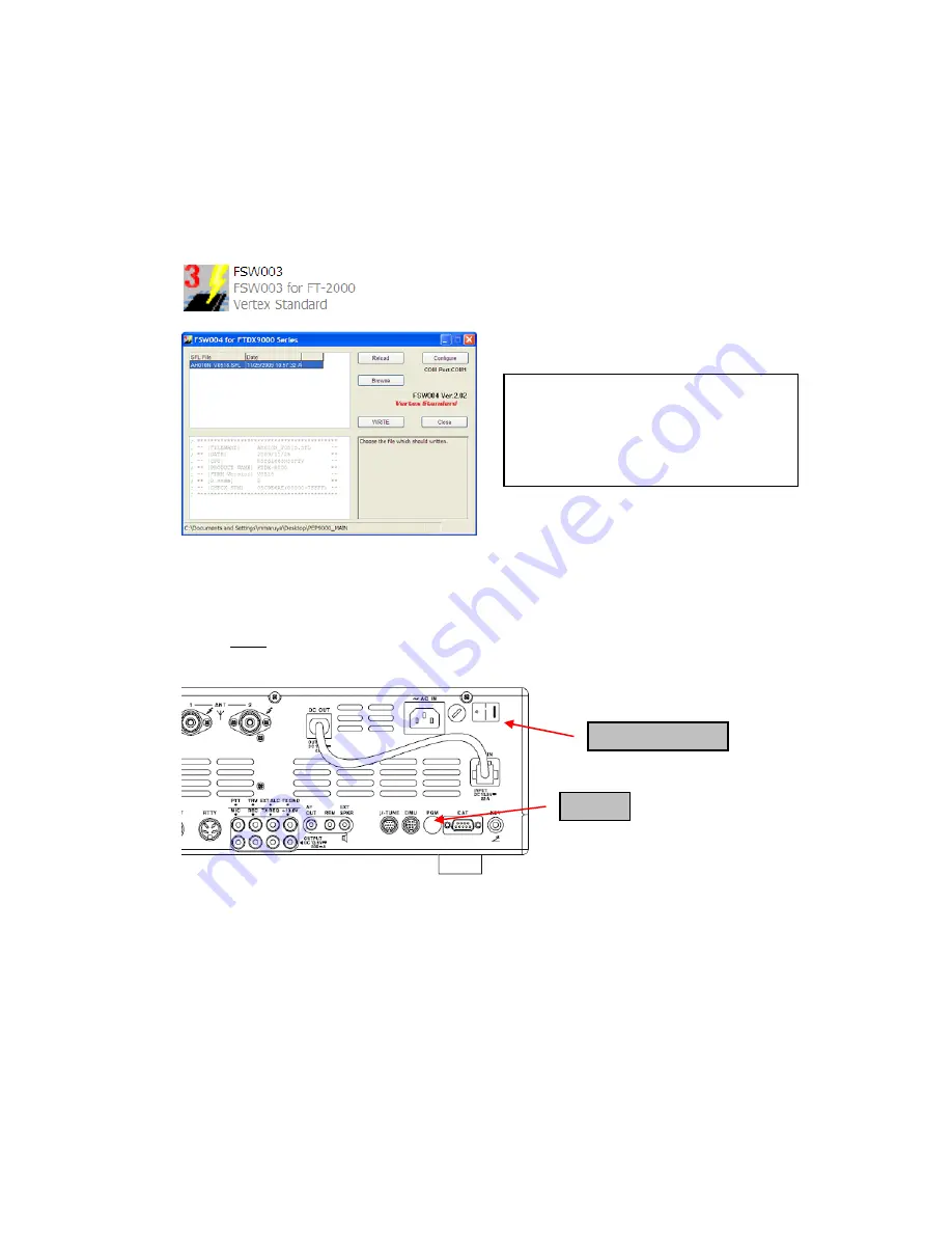
Turn off the main power switch located on the back of the FT

-

2000 (or turn off the power 

supply for FT

-

2000D and wait a minute, until the capacitors discharge) and remove the AC 

power cord.


(2) Connect 

the 

CT

-

119 Cable’s DB9F connector to the serial port COM1 in the back of your 

computer. If you use a USB to serial adapter, you might need to change the COM Port number.  

(3)   Now go to the desktop open PEP2000_MAIN folder and find the 

FSW003

 icon as shown 

below. Double-click


the FSW003


icon, displayed on the Program Screen. 


(4)   When the program opens, confirm that the file AH025_V0150.SFL is highlighted; if not, click 

on it to highlight it. 

(5)


Remove the black cover from the PGM jack (bottom left on the rear panel). Plug the mini-DIN 
connector of the CT-119 into the PGM jack. Be sure that the 

arrow

 indicator on the mini

-

DIN 

plug is 

down

. Plug the AC cord into the radio and turn the main power switch on the back of the 

radio to the ON position. [NOTE: The radio will not show a display now.] 


(6) 

Click on [WRITE] in the program window. A status bar with green bars should appear below 
the [WRITE] button. 

Note disregard the on screen instruction to [3. Turn “S3004” on]. 

(7)  

When the loading process is complete, an [OK?] box will appear. Click [OK?].  

(8)   Turn off the main power switch, (or turn off the power supply for FT

-

2000D and wait a minute, 

until the capacitors discharge) and unplug the AC power cord.  

(9)  

Unplug the CT

-

119 from the radio. 

(10)   Plug the AC power cord into the radio and turn the main power switch on the back of the radio 

to the ON position (or turn on the power supply for FT

-

2000D). 

(11)   Plug the radio back in. Press and hold in the [FAST] and [LOCK] keys; while holding them in, 

press the front power switch to turn the radio on. This resets the radio and locks in the new 
software. 

PGM

Main Power SW 

NOTE:

 I

f you receive a “communications 

error” message on your screen, click on the 

Configure

 box and choose a different COM 

port from the drop down menu. Then click the 
WRITE button again. 


Summary of Contents for FT-2000D - UPDATE V0150 AND V11.53

Page 1: ...om indexVS cfm cmd DisplayProducts ProdCatID 102 encProdID 66EA 91711DFB68C03DED4AD35153E12C DivisionID 65 isArchived 0 2 Save the FT 2000 data file FT 2000_PEP2000_11 30 09 zip to the desktop on your...

Page 2: ...ES Rotate the METER switch to select COM Compression We recommend setting the PROC level within the 5dB to 10dB range When menu settings are saved on the DMU 2000 CF card and transferred to the new ve...

Page 3: ...power switch on the back of the radio to the ON position NOTE The radio will not show a display now 6 Click on WRITE in the program window A status bar with green bars should appear below the WRITE b...

Page 4: ...hange the COM Port number 3 Reconnect the power cord and turn ON the main power switch located on the back of the FT 2000 or turn ON the power supply for FT 2000D 4 While holding the DNR CONT DNF butt...

Page 5: ...capacitors discharge and remove the AC power cord This resets the radio and locks in the new software Remove the DB9F to DB9F cable The updating process is now complete It is important to reset the FT...

Page 6: ...crease your enjoyment of your FT 2000 D Thank you for choosing Yaesu radios If you have any problems or questions please contact Vertex Standard Amateur Tech Support amateurtech vxstdusa com Best rega...

Page 7: ...located on the back of the FT 2000 or turn off the power supply for FT 2000D and wait a minute until the capacitors discharge and remove the AC power cord 2 You must access the programming switch S30...

Page 8: ...ntil the capacitors discharge 13 Switch the programming micro switch S3004 to the off position 14 Remove DB9F straight cable from the CAT connector on the rear of the transceiver 15 Replace the bottom...

Page 9: ...he left rear foot near the CAT connector to expose the program switch access hole Switch S3004 is visible through the hole Move the switch to the on rear position Top of picture This is just a screw h...

Reviews: