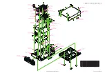
FC-50 Technical Supplement
Specifications
SPECIFICATIONS-1
Frequency Range:
1.8 MHz - 29.7 MHz, 50 MHz - 54 MHz
Input Impedance:
50 Ω
Maximum Power:
100 Watts
Tune-up Power:
4 W - 60 W
Tune-up Time:
5 seconds or less
Impedance Matching Range:
1.8 - 29.7 MHz = 16 Ω - 150 Ω
50 - 54 MHz = 25 Ω - 100 Ω
Impedance Matching Memories:
100 channels
Input Voltage Requirement:
13.8 V ±15% (supplied from transceiver)
Operating Temperature Range:
14 °F to +122 °F (-10 °C to +50 °C)
Case Size (W x H x D):
6.1” x 1.8” x 8.3” (155 x 45 x 210.5 mm)
Weight (Approx.):
3 lbs (1.35 kg)
Specifications subject to change without notice or obligation.
Summary of Contents for FC-50
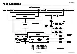
Page 4: ...BLOCK DIAGRAM 1 FC 50 Technical Supplement Block Diagram ...
Page 5: ...CONNECTION DIAGRAM 1 FC 50 Technical Supplement Connection Diagram ...
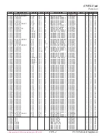
Page 6: ...FC 50 Technical Supplement CNTL 1 CNTL Unit Circuit Diagram ...
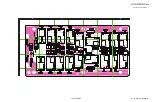
Page 7: ...FC 50 Technical Supplement CNTL 2 CNTL Unit Parts Layout side A 1 2 3 4 A B C D E F G H ...
Page 8: ...FC 50 Technical Supplement CNTL 3 CNTL Unit Parts Layout side B ...
Page 12: ...FC 50 Technical Supplement CAPACITOR 1 CAPACITOR Unit Circuit Diagram ...
Page 14: ...FC 50 Technical Supplement CAPACITOR 3 CAPACITOR Unit Parts Layout side B ...
Page 17: ...FC 50 Technical Supplement COIL 1 COIL Unit Circuit Diagram ...
Page 18: ...FC 50 Technical Supplement COIL 2 COIL Unit Parts Layout Side A Side B ...


