background image

DR-2X / DR-2XE Operating Manual

34

16. Set Up Various Functions

Using the setup menu, the various functions of the repeater can be customized to match the desired applications.  

Items to be adjusted can be selected from the respective lists, and the settings entered or selected that are 

appropriate for the intended repeater operation.

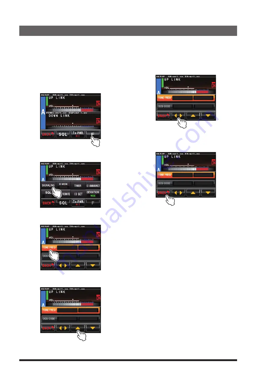
1

 Touch [

A SETUP

] or [

B SETUP

] on the operation 

mode screen.

  The setup mode screen will appear.

2

 Touch [

F

].

  The setup menu will appear.

 8

4  

 3

4  

3

  Touch the menu item.

  The menu list will appear.

 8

4  

D G - I D

T - O F F

R - O FF

4

  Touch the item to be set.

  The item will turn orange in color.

 8

4  

RX100.0Hz

TX100.0Hz

TX    023

RX    023

5

 Touch [

] or [

], or touch the item repeatedly.

  The set value will change each time it is touched.

 8

4  

RX123.0Hz

TX100.0Hz

TX    023

RX    023

6

 Touch [

◄ ►

] to select the item.

  The item will turn yellow in color.

 8

4  

RX123.0Hz

TX123.0Hz

TX    023

RX    023

7

 Touch [

BACK

].

  The setting is determined and the display will 

return to the setup menu.

 8

4  

RX123.0Hz

TX123.0Hz

TX    023

RX    023

Summary of Contents for DR-2X

Page 1: ...VHF UHF C4FM FM 50W AMS DIGITAL REPEATER Operating Manual...

Page 2: ...ge the remote command 28 12 Actual remote control procedure 29 Remote Control for C4FM Digital 29 Remote Control for Analog FM 29 13 Voice messages 30 Voice Message for C4FM Digital Mode 30 Voice Mess...

Page 3: ...eater System and easily managing a network of multiple connected repeaters About the touch panel Precautions in using the touch panel The touch panel of the controller is designed to work with the sli...

Page 4: ...etc Do not use the device when the power cord and connection cables are damaged and when the power connector cannot be plugged in tightly Please contact our company amateur customer support or the ret...

Page 5: ...he equipment rack or shelf with bolts z z Mounting on rack or shelf z z Mounting on a desk Whenusingtherepeater in a desktop location in stead of a rack or shelf attach the four supplied legs onto the...

Page 6: ...ntenna into the jack of the duplexer and turn to tighten From RX ANT Duplexer To antenna From TX ANT Select downlink antenna Normally the CH A downlink outputs to the CH A TX Antenna Terminal and the...

Page 7: ...rom a battery or DC supply the repeater requires approximately 14A at 13 8V during transmit Always observe proper polarity when making DC connections z z Use a power source capable of supplying DC 13...

Page 8: ...utside the specified range of 13 8 V 15 When replacing fuses be certain to use a fuse of the proper rating The DR 2XE requires a 15A blade fuse Connecting External Devices Connection of an external mi...

Page 9: ...switch the repeater ON and side to switch the repeater OFF LED Indicator When the indicator illuminates in green the power is supplied from the AC IN jack DR 2X only When the indicator illuminates in...

Page 10: ...ontrol RX channel of the CH B with the coaxial cable ACC Jack Connect to a HRI 200 WIRES X Interface Unit or a personal computer with the provided PC connection cable SCU 20 CONTROL I O Connector This...

Page 11: ...ID call sign setup begins with 2 1 Touch A SETUP or B SETUP to display Frequency screen 2 Touch F to display the Function screen pops up 8 4 3 4 3 Touch ID set area The character input screen will app...

Page 12: ...pears To reset touch the area again CH B CH A TX downlink RX uplink TX downlink RX uplink To receive Analog FM and Digital C4FM signals simultaneously set RX to AUTO mode This mode may activate the AM...

Page 13: ...equipped with dual receive feature that may receive two different frequencies in the VHF and the UHF Band of Amateur radio bands so the other uplink and downlink frequency for emergency communications...

Page 14: ...quency is used Select downlink antenna Normally downlink of CH A outputs to the CH A TX Antenna Terminal and the downlink of CH B outputs to the CH B TX Antenna Terminal Both CH A and CH B downlinks m...

Page 15: ...n the operation setup screen PRI appears and this channel is set to the Priority channel To deactivate the Priority channel touch the same area to unset PRI and return to normal operation Priority mod...

Page 16: ...e SQL meter and show the squelch level setting 3 Touch or to adjust the squelch level The level will be displayed in the SQL meter 4 Touch BACK The squelch level is set and the display will return to...

Page 17: ...can be used as a VHF UHF base station by connecting an optional MH 48A6JA or MH 42C6J microphone to the MIC jack on the front panel z z The base mode operation is available only on CH A z z For Base S...

Page 18: ...are not grouped together may be used by other transceivers In using this convenient feature the DG ID TOT Time Out Timer allows temporary intercommunication between all the grouped repeaters by cance...

Page 19: ...istered to the DR 2X DR 2XE repeater When using the DR 2X DR 2XE as an Open Repeater that anyone may use set the DG ID to 00 Name MY RPT BACK BACK DG ID 01 Down Link OWN LOCAL RPT DG ID 5 Touch Name t...

Page 20: ...K BACK DG ID 10 Down Link OWN Group 1 DG ID Register setting DG ID group 1 Touch A SETUP or B SETUP to display the frequency set up screen then touch F on the bottom of the screen 2 keep touching ID M...

Page 21: ...D list screen appears 10 Touch BACK The DG ID setting is saved and the display will return to Group DG ID setting screen DG ID EDIT Space 10 20 50 3 11 Touch Group name twice The character input scree...

Page 22: ...en then touch F on the bottom of the screen 2 Touch TIMER 8 4 DG ID T O F F R OFF 3 Touch TOT TIMER TOT SQL MESSAGE BACK BACK 4 Touch IMRS TOT 5 Touch or to select TOT time Selectable from 0 30sec 1mi...

Page 23: ...peater DP ID log 1 Touch A SETUP or B SETUP to display the frequency set up screen then touch F on the bottom of the screen 2 Touch ID MODE to select the DP ID Touching ID MODE switches the setting as...

Page 24: ...te or touch the Cancel to return to the DP ID list screen without deleting If deleting another transceiver repeat step 4 to 5 6 Touch BACK The screen returns to the setup screen DTMF 2222 3333 4444 1...

Page 25: ...the transmit DG ID default to 00 and the receive DG ID to 00 The examples of the user operation with the above settings z z The group members USER 1 USER 2 and USER 3 may communicate the normal opera...

Page 26: ...mit the downlink signal These settings are retained even if the other members transmit the uplink signal from RPT A and RPT D with any DG IDs during the time set by the TOT LOCAL DG ID 04 RPT D UPLINK...

Page 27: ...downlink signal from all the linked repeaters When RPT D is performing local communication etc and TOT is activated it cannot be accessed from other repeaters Transceiver beeps 3 times to notify that...

Page 28: ...FM C4FM digital 1 Touch A SETUP or B SETUP on the operation mode screen The setup mode screen will appear 2 Touch F in the setup mode screen The setup menu will appear 3 Touch MODE REMOTE The menu lis...

Page 29: ...local repeater operation 2222 2222 Local Deactivate Set S DEACTIVATE ALL Deactivate all the linked repeat ers 2221 1 All Deactivate Set FIX DIGITAL Set the repeater to C4FM mode 3333 3333 DIGI DIGI Se...

Page 30: ...appear M V BACK BACK REMOTE COMMAND DISP TIMER OFF ON REMOTE COMMAND DISPLAY TIMER 5 Touch t u to select the desired CONTROL MODE DIGITAL or DTMF 6 Touch or to select the desired command 7 Touch the...

Page 31: ...he FTM 100D 1 Please confirm that the FTM 100D DP ID is registered on DR 2X DR 2XE repeater 2 Tune the transmit frequency of the FTM 100D to the uplink frequency of the CH B side of the DR 2X DR 2XE 3...

Page 32: ...e P3 key is pressed the recorded contents are deleted and CLEAR Completed is displayed on the screen of the mobile transceiver 3 Press the key on the microphone to return to the normal operation Voice...

Page 33: ...ows then select the desired number of announcements 0 5 hour 1 hour 2 hour 3 hour The default setting is 1 hour 5 Touch BACK 4 times The screen returns to the operation mode screen MESSAGE 5times 1hou...

Page 34: ...microphone uPLAY will change to REC Speak into the microphone the message is recorded until you release the PTT switch Recording is possible for a maximum of 60 seconds DTMF 1111 2222 3333 4444 CONTR...

Page 35: ...ayed at the bottom of the screen 8 4 DG ID T O F F R OFF 6 Touch and hold uPLAY CLEAR ALL VOICE will be displayed DTMF 1111 2222 3333 4444 CONTROL MODE ACTIVATE DEACTIVATE FIX DIGITAL AUTO PLAY 7 Touc...

Page 36: ...p mode screen will appear 2 Touch F The setup menu will appear 8 4 3 4 3 Touch the menu item The menu list will appear 8 4 DG ID T O F F R OFF 4 Touch the item to be set The item will turn orange in c...

Page 37: ...t value will change each time or is touched 5 Touch BACK 3 times The setting is determined and the display will return to the operation mode screen z z Factory default 100 0 Hz z z Tone frequencies be...

Page 38: ...log FM mode Set the announcement mode 1 Touch A SETUP or B SETUP then touch F and then touch ID ANNOUNCE 2 Touch ANNOUNCE then touch ANNOUNCE MODE The set value will change in the following sequence e...

Page 39: ...he SQL HYSTERESIS 1 Touch A SETUP or B SETUP then touch F and then touch TIMER 2 Touch SQL twice 3 Touch SQL HYSTERESIS The set value will change in the following sequence each time SQL HYSTERESIS or...

Page 40: ...e returned to the factory default state z z Use the factory default password 0000 unless it is necessary to change it for management security 1 Touch A SETUP or B SETUP then touch F and then touch MOD...

Page 41: ...ntinue pressing the SETUP button until the operation mode screen appears on the display SETUP POWER 3 Touch A SETUP The setup mode screen will appear 4 Touch F in the setup mode screen The setup menu...

Page 42: ...arge capacity Internet line and the HRI 200 must always be connected to the computer it may be advantageous to set up the HRI 200 in a different location and uplink it to the repeater with the Node St...

Page 43: ...MODE will appear on the display 4 Touch OK HRI mode will activate X C 6 D W O K HRI REPEATER MODE Cance Return to REPEATER mode from HRI mode 1 Turn the DR 2X DR 2XE power OFF 2 While pressing and ho...

Page 44: ...ion is not available in the HRI REPEATER MODE M V BACK BACK ON ON REMOTE COMMAND DISPLAY TIMER REMOTE COMMAND DISP TIMER 5 Touch BACK 3 times The setting is determined and the display will return to t...

Page 45: ...to this pin and connect the shield to GND AF IN is usually used for analog modulation input with a packet speed of 1200 bps however to input C4FM digital signals for digital modulation operations refe...

Page 46: ...or interfering signal while in Repeater mode Pin 1 may be grounded by external control to temporarily disable repeating the receiver input Transmitting C4FM digital signals For digital modulation ope...

Page 47: ...pin 7 GND DR 2X DR 2XE GND pin 8 DISC OUT pin 8 TX pin 8 Select TX LOGIC or TX CTCSS by JP pin pin 9 AF OUT pin 9 GND DR 2X DR 2XE GND pin 10 GND I O Controller pin 1 to 6 Logic output Connect to DR...

Page 48: ...2X DR 2XE Operating Manual 46 Connecting S COM7330 RS232 1 RS232 2 ID PORT 1 PORT 2 PORT 3 RESET INIT DC 9V 36V S COM7330 This connection needs programming of S COM7330 Repeater 1 Repeater 2 Repeater...

Page 49: ...C to 60 C DR 2XE 20 C to 55 C Dimensions 19 W 3 5 H 15 D 482 88 380 mm w o knob connector handle Weight approx DR 2X 20 72 lbs 9 4 kg DR 2XE 18 52 lbs 8 4 kg z z Transmitter RF power output 50 20 5 W...

Page 50: ...charge within a 3 year period from the date of purchase Keep the warranty certificate in a safe location When the warranty certificate is lost failures which occur during the warranty period will be t...

Page 51: ...bject to the following two conditions 1 This device may not cause harmful interference and 2 this device must accept any interference received including interference that may cause undesired operation...

Page 52: ...the permission of YAESU MUSEN CO LTD YAESU MUSEN CO LTD Tennozu Parkside Building 2 5 8 Higashi Shinagawa Shinagawa ku Tokyo 140 0002 Japan YAESU USA 6125 Phyllis Drive Cypress CA 90630 U S A YAESU U...

Reviews: