


11
Warning:
-
The
antenna
must be fixed to a base/support by tightening the screw
in the base of the
YachtConnect
by means of a screwdriver (
Fig. 6
).
-
The installation of the
YachtConnect
near or above a flat metal
surface
may result in significant reduction of the Wi-Fi and 3G/4G
s
ignal
st
re
ngth.
-
Do not mount the
YachtConnect
near metal obstructions that may
interfere with the wi-fi signal
On metal crafts, the Wi-Fi signal is blocked, for this reason it is necessary to
place a second access point (up to a maximum of 4 APs) inside the boat and
connect them with a switch (optional) to the router inside of
YachtConnect
via an
Ethernet cable (optional) (Fig. 9). The access point present
inside the
radome can be used for the Wi-Fi coverage outside the boat.
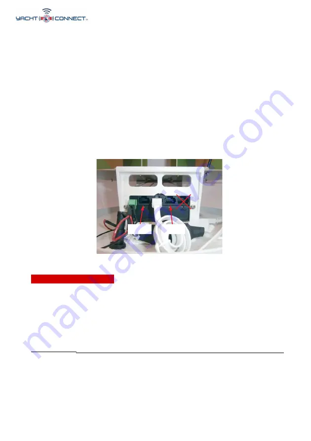
Electric connections
For the proper functioning of
YachtConnect
, simply connect the antenna to
a 12/
24 Vdc power supply cable (not provided) according to the following
guide-lines.
Connect the
brown
(positive) and the b
lue
wire (negative) coming out from
the
base of
YachtConnect
to the battery through a red/black power cable.
The connection can be made by soldering or with a clamp. It is advisable to
have this
procedure carried out by a technician.
IMPORTANT
:
A
polarity reversal on the power supply will burn the fuse.
The power line (not supplied) which connects the two wires coming out from
the base of
YachtConnect
must have cables with a cross section of 1.5 mm²
by a
length up to
33 ft
, and 2.5 mm² for longer lengths.
WARNING
: we recommend placing a switch
in the power line,
upstream
to
avoid electricity consumption when the
YachtConnect
is not used.
GL00187
LAN1
LAN3
Fig. 9