


Skystream Owner’s Manual
3-CMLT-1054 Rev O XCO 1191
Pg. 41
ground level unless the above ground end and grounding electrode conductor are protected
against physical damage as specified below (quoted from 2005 NEC article 250.10):
a)
In installations where they are not likely to be damaged
b)
Where enclosed in metal, wood, or equivalent protective covering
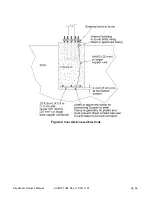
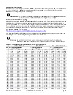
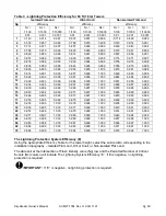
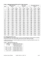
2-1-2 Electrode Resistance to Ground
The resistance to earth of a single ground rod can be calculated using
Dwight’s equation:
R = [r/(2
ϖL)]x[ln(4
L
/R)-1], where r is the soil resistivity, L is the length of the rod buried inside the
earth and R = radius of the rod; ln stands for the natural logarithm.
For calculating the resistance of the rod to ground, one must know the value of soil resistivity.
This may be found in the local electrical code or building
inspector’s office/municipal office or by
an actual soil resistivity test.
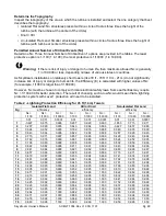
The resistance of a rod electrode to ground may be lowered by increasing the rod diameter,
increasing the buried length of the rod or by treatment of the soil to reduce its resistivity.
If the single chosen electrode does not have a resistance to ground of 10 ohm or less, it shall be
augmented by additional electrodes as necessary. The overall resistance of multiple rods to
ground would roughly equal the resistance of a single rod to ground divided by the number of
rods. Where multiple such electrodes are installed to meet the above requirement, they shall not
be less than 1.8 m apart. The multiple rods must be bonded together using the grounding
electrode conductor.
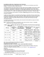
2-1-3 Grounding Electrode Conductor:
Material, Size, Bonding to Electrode and Bonding to Tower
Material (Ref. 2005 NEC articles 250.62, 250.96(A).
The grounding electrode conductor shall be of copper, aluminum, or copper-clad aluminum. The
material selected shall be resistant to any corrosive condition existing at the installation or shall
be suitably protected against corrosion. The conductor shall be solid or stranded, insulated,
covered or bare. Any non-conductive paint, enamel, or similar coating shall be removed at
threads, contact points, and contact surfaces or be connected by means of fittings designed so
as to make such removal unnecessary.
Note:
Many local electrical standards do not permit the use of aluminum or copper-clad
aluminum conductors and strictly require the use of copper conductors.
2-1-4 Conductor Size
(Ref. 2005 NEC article 250.66(A)):
Where the grounding electrode conductor is connected to rod, pipe or plate electrodes, that
portion of the conductor that is the sole connection to the grounding electrode shall be a
minimum of 6 AWG copper wire or 4 AWG aluminum wire.
2-1-5 Bonding the Grounding Electrode Conductor to the Earth Electrode
(Ref. 2005 NEC article 250.70):
The grounding or bonding conductor shall be connected to the grounding electrode by
exothermic welding, listed lugs, listed pressure connectors, listed clamps, or other listed means.
Connections depending on solder shall not be used. Ground clamps shall be listed (approved)
for the materials of the grounding electrode and the grounding electrode conductor and, where
used on pipe, rod or other buried electrodes, shall also be listed for direct soil burial.