


User Manual
Power modules for heating and cooling meters
PolluTherm / PolluStat E / PolluFlow
M H 6122 INT, page 2
3. Retrofitting or replacement of a power module
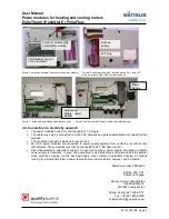
3.1. Opening of the calculator housing
Remove the lower user seal from the housing
Calculator housing 1: Open housing cover by opening the black housing latch
Calculator housing 2: Open housing by pressing both closing clips at the two bottom corners
3.2. Removal of battery and insert of power module
Calculator housing 2:
PolluStat E, PolluFlow, PolluTherm: before the supply battery is removed the calculator module has
to be dismantled from the calculator. PolluTherm (delivery from 2007 to 2010): the integrator module
has to be changed with a new one (from 2010 on). Unscrew only the screw from the plastic cover on
the right side under the KK1 seal (user seal) (picture 3). Pull out the calculator module. The seals in
the middle and on the left side may not be removed (invalidation of metrological sealing)!
PolluStat E, PolluFlow, PolluTherm (from 2010 on): plug on the back-up battery AA 3,6V (68504900)
to the backside of the calculator module (picture 4) (JST plug). The battery is required for date back-
up and short-term emergency operation in power failures. In PolluTherm (2007 to 2010) the back-up
battery is soldered-on to the circuit board as standard. These modules cannot be retrofitted to mains-
power supply.
Calculator housing 1 and 2:
Lift the battery or the power module and disconnect the output plug
For disposal note safety instructions, point 2
3.3. Installation of power supply unit
Plug the connection plug of the power module in the socket and insert the power module in the
designated recess of the housing.
In order to connect cables a spare rubber moulding has to be removed from the calculator housing 2.
Guide the cable through the rubber moulding and provide a strain relief with the cable binder.
Calculator housing 1: the cable has to be guided through the PG screw connection and fixed.
Plug the cable of the output plug in the supply plug (due to the different pins interchanging of the
power supply units is not possible).
Please ensure that the cable of the connection plug is not pinched by the calculator cover.
Close the calculator lid and seal with the provided self lock seal.
For detection of the power module it is necessary that the device is connected to the power system
for at least one minute.
Through a connector encoding the M-Bus credit automatically turns off when a power supply unit is
installed.
Picture 1: inside view with battery, calculator housing 2
Picture 2: inside view with power module, calculator housing 2
Connection plug
battery / power module
Battery:
C or D
Power
module


