background image

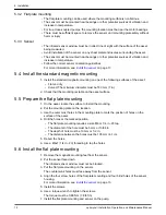
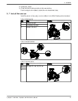
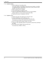
7.1.3  Install the battery

1. Install the batteries into the battery holder.

The positive terminals of the batteries must face the power connectors on the PCB.
The negative terminals of the batteries must face the 5 V power connector located

opposite of the battery connection pins.

2. Attach the battery clip on the batteries.
3. Check that the battery clip engages correctly.
4. Attach the supplied adhesive foam strips on the top of both the batteries.

Distance must be 0.5 cm (1/4 in) from the end of each battery.

5. Plug the white connectors of batteries on the PCB.

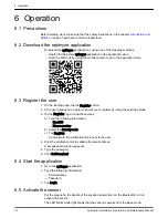
7.1.4  Install the cover

1. Install the new gasket in the gasket groove of the lower cover.
2. Carefully install the upper cover on the lower cover.

The outer rim of the cover must surround the lip of the lower cover.
The Xylem logo must align with the external power supply connector.

3. Use the T10 screw driver to install the screws on the cover.
4. Tighten the screws diagonally opposite of one another to prevent rolling or pinching of

the gasket.

5. Use a torque wrench to tighten the screws of the cover.

The torque must be 0.88 Nm (7.8 lbf.in).

7  Maintenance

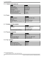
18

optimyze

 Installation, Operation, and Maintenance Manual

Summary of Contents for optimyze

Page 1: ...Installation Operation and Maintenance Manual P2007013_1 0 optimyze...

Page 2: ......

Page 3: ...nu 9 5 Installation 11 5 1 Precautions 11 5 2 Mounting options 11 5 3 Requirements 11 5 3 1 Standard magnetic mounting 11 5 3 2 Flat plate mounting 12 5 3 3 Sensor 12 5 4 Install the standard magnetic...

Page 4: ...22 9 6 Power 22 9 7 Wireless communication 22 9 8 Physical properties 22 9 9 Part numbers 22 10 Product Warranty 23 11 Cybersecurity 24 12 Certifications 25 12 1 For US and Canada only 25 12 1 1 FCC I...

Page 5: ...Safety terminology and symbols About safety messages It is extremely important that you read understand and follow the safety messages and regulations carefully before handling the product They are p...

Page 6: ...and in use at all times when the unit is being operated 1 4 Protecting the environment Emissions and waste disposal Observe the local regulations and codes regarding Reporting of emissions to the appr...

Page 7: ...original spare parts to replace any worn or faulty components The use of unsuitable spare parts may cause malfunctions damage and injuries as well as void the warranty 1 Introduction and Safety optim...

Page 8: ...emove packing materials from the product Dispose of all packing materials in accordance with local regulations 2 To determine whether any parts have been damaged or are missing examine the product 3 I...

Page 9: ...em Graphical trending and waveform analysis Generates reports Shows maintenance logs Library of product documentation IOM data sheet and parts Schedules the routine preventive maintenance of assets 3...

Page 10: ...set vibration has increased to warning level Red Shows that the asset vibration has increased to critical level Green Shows that the battery level is normal Red Shows that the battery level is low Sho...

Page 11: ...dial Axial and Horizontal Shows the last recorded RMS vibration level Allows user to access the vibration trend charts for RMS Kurtosis and FFT Battery life Shows the last recorded battery level Allow...

Page 12: ...the approved vibration thresholds for normal operation For more information see Vibration threshold selection on page 16 If an incorrect power rating or classification is selected the sensor may show...

Page 13: ...ical implants WARNING The magnets in the sensor feet are extremely powerful Beware of serious injury to fingers and hands When not in use keep magnetic ferrous components and magnetized tools apart by...

Page 14: ...stable on the asset surface 5 5 Prepare the flat plate mounting 1 On the asset locate the surface to install the mounting 2 Put the mounting plate on the location 3 Use the outer most holes in the mo...

Page 15: ...or on the pump or motor surface in one of the following correct positions Table 1 Default position Axis Align Position X Axially to the shaft Y Horizontally to the shaft Z Radially to the shaft Table...

Page 16: ...ng the existing details 3 On the Register page follow these steps a Type the following information Email ID Phone number b Select the Country code c Tap Register An email with the verification link is...

Page 17: ...t serial number The serial number is located below the QR code 4 Tap Enter A blinking blue LED shows that the mobile phone is connected to the sensor 5 On the Bluetooth Pairing Request screen tap the...

Page 18: ...ard Pump type Vibration velocity mm s and LED color LED Power rating 200 kW Power rating 200 kW 1 ISO 10816 7 Category 1 critical Green 4 0 5 0 Yellow Between 4 0 and 6 6 Between 5 0 and 7 6 Red 6 6 7...

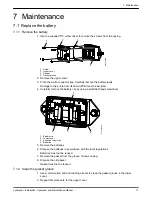
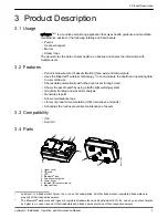
Page 19: ...clip by using a small flat head screwdriver 1 2 3 WS013248A 4 1 Battery clip 2 Lower cover 3 Adhesive foam strip 4 Batteries 5 Remove the batteries 6 Dispose the batteries in accordance with the local...

Page 20: ...e end of each battery 5 Plug the white connectors of batteries on the PCB 7 1 4 Install the cover 1 Install the new gasket in the gasket groove of the lower cover 2 Carefully install the upper cover o...

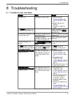
Page 21: ...red The soft keyboard on the phone screen hides the Enter button at the bottom of the screen Tap Done button or the background to close the soft keyboard Cannot find the device try again message is sh...

Page 22: ...oth icon 1 Move the magnet away from the sensor for a short duration and then try again 2 Hold the magnet along the side wall of the sensor near the Bluetooth icon The sensor does not turn on after th...

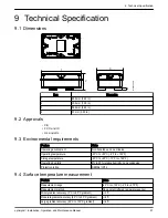
Page 23: ...Storage temperature 25 C to 65 C 13 F to 149 F Operating humidity 5 to 95 relative humidity non condensing Protection rating NEMA4 IP56 9 4 Surface temperature measurement Feature Value Measurement ra...

Page 24: ...nit of time 10 seconds to 12 hours 9 7 Wireless communication Feature Description Network type Bluetooth Low Energy 5 01 2 4 GHz ISM band RF 3 29 mW 5 17 dBm Connection range without interference 30 m...

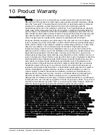
Page 25: ...the Warranty are warranted only for the balance of the warranty period on the parts that were repaired or replaced Seller shall have no warranty obligations to Buyer with respect to any product or pa...

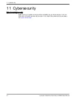
Page 26: ...system security and the availability of your critical services For more information on Xylem cybersecurity practices or to contact the cybersecurity team please visit xylem com security 11 Cybersecur...

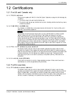
Page 27: ...required to correct the interference at their expense 12 1 3 FCC IC RF radiation exposure statement The device shall be used in such a manner that the potential for human contact normal operation is...

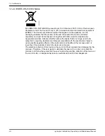
Page 28: ...e device that is no longer used to be subjected to recycling treatment and disposal compatible with the environment helps to avoid possible negative effects on the environment and health and favors re...

Page 29: ...5 EU of 8 June 2011 restriction of the use of certain hazardous substances in electrical and electronic equipment and subsequent amendments 6 References to the relevant harmonized standards used or re...

Page 30: ......

Page 31: ......
Page 32: ...mart metering network technologies and advanced analytics solutions for water electric and gas utilities In more than 150 countries we have strong long standing relationships with customers who know u...

Reviews: