


1
10
11
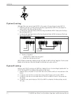
Control to boiler wiring
Warning:
• Fire hazard. Electrical wiring must have a rating of 167ºF (75ºC) if the liquid exceeds
180ºF (82ºC).
• When installing jumper wire make sure you are not introducing a second voltage source
into the burner circuit and thereby bypassing other safety, limit, and operating controls.
Select a wiring method after reviewing the wiring diagrams and notes.
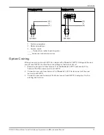
• Voltage of new manual reset LWCO must be the same as the existing automatic reset
LWCO.
• Make sure the Factory jumper bar is installed on the existing auto reset probe type
LWCO connecting terminals H and C. If there is no jumper bar connecting Terminals H
and C, then consult the factory to discuss wiring options.
• For Option B, the power to the automatic reset LWCO turns off when the new manual
reset LWCO detects a low water condition. The water feeder does not operate until the
new manual reset LWCO detects water on the probe.
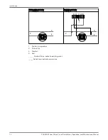
• For options A and C, the power to the new manual reset LWCO turns off when the
existing auto reset LWCO detects a low water condition, reducing the chance of
nuisance lockouts. The water feeder continues to operate because there is still power
to the existing auto reset LWCO. Power to the new manual reset LWCO is restored
when the auto reset LWCO detects water on the probe.
Electrical conduit connections
• Connect electric conduit using knockouts provided.
• Follow accepted electrical practices for installation of fittings and connections.
• Refer to and follow local codes and standards when selecting the types of electrical
fittings and conduit.
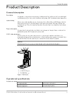
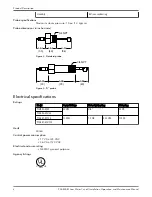
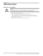
Wire connections to the terminal block
Use the following instructions for all wire connections to the terminal block.
1. Strip about 1/3” (8.5 mm) of insulation from the wire.
2. Loosen the terminal screw (2) but do not remove it.
3. Move the wire clamping plate (3) back until the plate touches the back side of the
screw head.
4. Insert the stripped end of the wire between the terminal block (1) and the wire
clamping plate (3).
5. Tighten the terminal screw (2).
Installation
PSE-800-M Low Water Cut-off Installation, Operation, and Maintenance Manual
9
Summary of Contents for McDonnell & Miller PSE-800-M
Page 1: ...PSE 800 M Low Water Cut off Installation Operation and Maintenance Manual...
Page 2: ......
Page 18: ......
Page 19: ......


