

A
D
2
INSTALLATION –
TOOLS NEEDED:
One (1) tube cutter, one (1) pencil, one (1) flathead
screwdriver, one (1) adjustable wrench and two (2)
pipe wrenches.
The Series 67 and Series 767 low water cut-offs are
float-type boiler controls designed to interrupt current
to the burner whenever the water drops to the cut-off
level.
The Series 767 is identical to Series 67 in all
respects except one. The Series 767 is equipped with
a 2-1/2" (63.5mm) pipe tap opening in the body, and
does not require the quick hook-up fittings supplied
with the Series 67. The pipe tapping allows for a
direct connection to the side of the boiler.
Electrical Ratings
Pump Circuit Rating (Amperes)
Voltage
Full Load
Locked Rotor
Pilot Duty
125 VA at
120 or 240 VAC
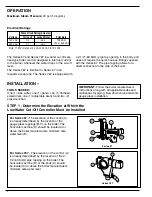
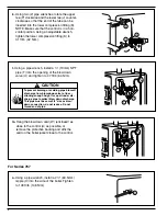
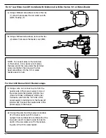
For Series 67 -
The elevation of the control (A)
is already determined by the location of the
gauge glass tappings (B,C) on the boiler. The
horizontal cast line (D) should be located at or
above the boiler manufacturer's minimum safe
water level (E).
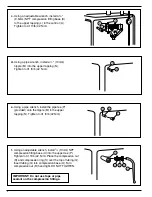
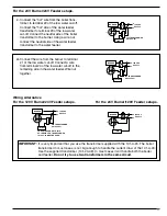
For Series 767 -
The elevation of the control (A)
is already determined by the location of the 2-
1/2 (63.5mm) pipe tapping on the boiler. The
horizontal cast line (D) of the body (A) should
be located at or above the boiler manufacturer's
minimum safe water level.
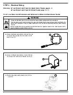
STEP 1 - Determine the Elevation at Which the
Low Water Cut-Off Controller Must be Installed
C
A
E
B
D
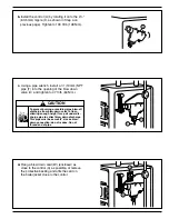
IMPORTANT:
Follow the boiler manufacturer's
instructions along with all applicable codes and
ordinances for piping, blow down valve and water
gauge glass installation.
OPERATION
Maximum Steam Pressure:
20 psi (1.4 kg/cm
2
)
Series 67
Series 767
Note: 11 MV is rated at 24 VA @ 24 VAC to 120 VAC
120 VAC
7.4
44.4
240 VAC
3.7
22.2


