


en - Translation of the original instructions
• Liquids not compatible with the pump construction materials
• Hazardous liquids (such as toxic, explosive, flammable, or corro-
sive liquids)
Standard/
Optional
Material
code
Material
casing/
impeller
EN733
range
Extension
range
32
–125 to
150-400
200
–250,
200
–315,
250
–315
• Potable liquids other than water (for example, wine or milk)
Examples of improper installation:
• Hazardous locations (such as explosive, or corrosive atmos-
pheres).
• Location where the air temperature is very high or there is poor
ventilation.
• Outdoor installations where there is no protection against rain or
freezing temperatures.
Standard
Standard
Standard
CC
CB
CN
Cast iron /
Cast Iron
X
X
X
Cast Iron /
Bronze
Cast Iron /
Stainless
Steel
DANGER:
Do not use this pump to handle flammable and/or explosive
liquids.
Standard
Standard
Standard
DC
DB
DN
Ductil Iron /
Cast Iron
X
X
X
NOTICE:
Ductil Iron /
Bronze
• Do not use this pump to handle liquids containing abrasive, solid,
or fibrous substances.
• Do not use the pump for flow rates beyond the specified flow
rates on the data plate.
Ductil Iron /
Stainless
Steel
Special applications
Standard
Optional
NN
RR
Stainless
Steel / Stain-
less Steel
X
X
Contact the local sales and service representative in the following cas-
es:
• If the density and/or viscosity value of the pumped liquid exceeds
the value of water, such as water with glycol; as it may require a
more powerful motor.
Duplex / Du-
plex
X
• If the pumped liquid is chemically treated (for example softened,
deionized, demineralized etc.).
3.6 Mechanical seal
• Any situation that is different from the ones that is described and
relate to the nature of the liquid.
Unbalanced single mechanical seal acc. EN 12756, version K Dimen-
sions. See
Table 10
.
3.2 Pump description
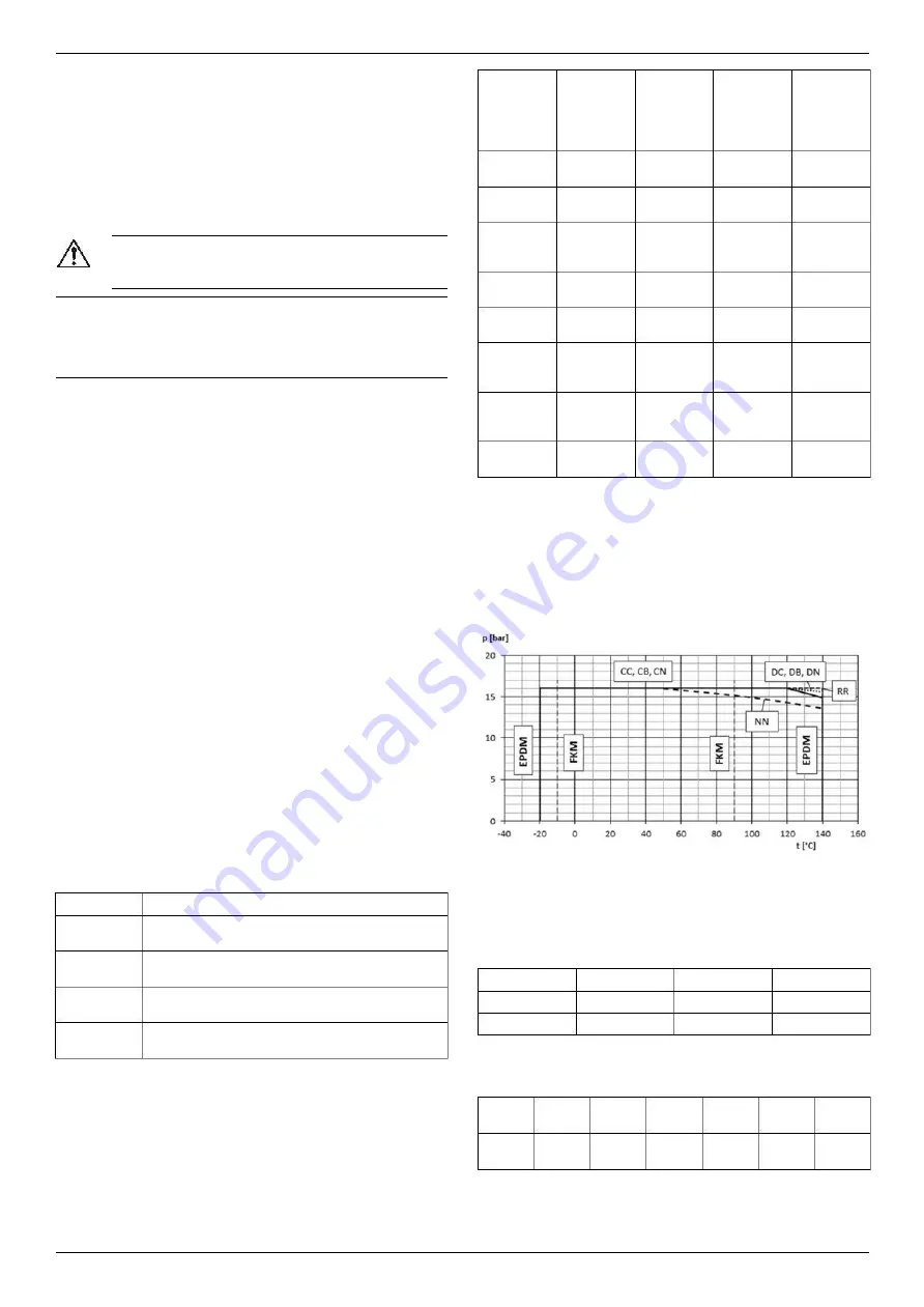
3.7 Application limits
See
Figure 6
for an explanation of the description code for the pump
and one example.
Maximum working pressure
This flow chart shows the maximum working pressure depending on
the pump model and the temperature of the pumped liquid.
3.3 Nameplate
The nameplate is a metal label that is located on the bearing bracket.
The name plate lists key product specifications. For more information,
see
Figure 7
The nameplate provides information regarding the impeller and casing
material, the mechanical seal and their materials. For more informa-
tion, see
Figure 8
.
IMQ or TUV or IRAM or other marks (for electric pump only)
Unless otherwise specified, for products with a mark of electrical-relat-
ed safety approval, the approval refers exclusively to the electrical
pump.
3.4 Design structure
• Dimensions according EN 733 and additional not standardized
extension sizes
• Volute casing pump with back pull out power end
• Single stage
• For horizontal assembly
P
1max
+ P
max
≤ PN
P
1max
P
max
PN
Maximum inlet pressure
Part
Description
Maximum pressure generated by the pump
Maximum operating pressure
Casing
• Radial split volute casing with radial discharge
• Replaceable wear ring
Liquid temperature intervals
Impeller
• Closed radial impeller with wear rings on both
sides
Version
Standard
Optional
Gasket
Minimum
Maximum
Shaft seal
Bearings
• Single mechanical seal acc. EN 12756
• Optional cartridge mechanical seal
EPDM
-20°C (-4°F)
-10°C (14°F)
140°C (284°F)
90°C (194°F)
FPM (FKM)
• Radial ball bearings of motor
• Grease lubrication
For special requirements, contact the Sales and Service Department.
See the sectional drawing
Figure 9
.
3.5 Material
kW
0.25 -
3.00
4.00 -
7.50
11 - 22 30 - 37 45 - 75 90
– 160
The metallic parts of the pump that come in contact with water are
made of the following:
Starts
60
40
25
16
8
4
per hour
Noise level
See the measuring surface sound pressure levels L
pA
in
Table 11
.
5
e1631 Installation, Operation, and Maintenance Manual
Summary of Contents for Lowara e1631
Page 1: ...K20040028 REV 0 ...
Page 27: ...Technical appendix 28 e1631 Installation Operation and Maintenance Manual 27 ...
Page 32: ......


