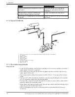
Make sure the shaft extends into the hubs at least 0.8 times the diameter of the shaft.
6. Lightly fasten the hubs to the shafts in order to prevent them from moving during
alignment.
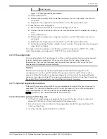
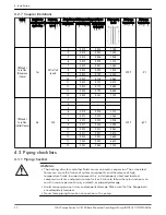
7. Align the hubs to the values shown in Maximum allowable misalignment for couplings.
You can perform alignment with lasers, dial indicators, or with a straight edge and
calipers.
4.2.2 Align the pump using a straight edge and calipers
For standard sleeve type coupler with black rubber insert
Before aligning the coupler, make sure there is at least 1/8” end clearance between the
sleeve and the two coupler halves.
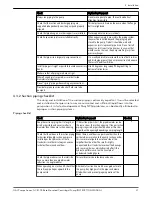
1. Check the angular misalignment:
Tool
Procedure
Calipers
1. Measure the outside of one flange to the outside of the opposite flange at four points 90°
apart. Do not rotate coupler. Misalignment of up to 1/64 per inch of coupler radius is
permissible.
Feeler
gauges
1. Insert feeler gauges between the coupling faces at various points around the circumference.
Do not rotate the shafts.
2. Reposition the equipment until the difference between the minimum and maximum
distance values is within the permissible range.
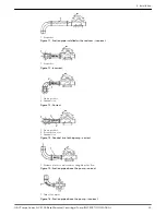
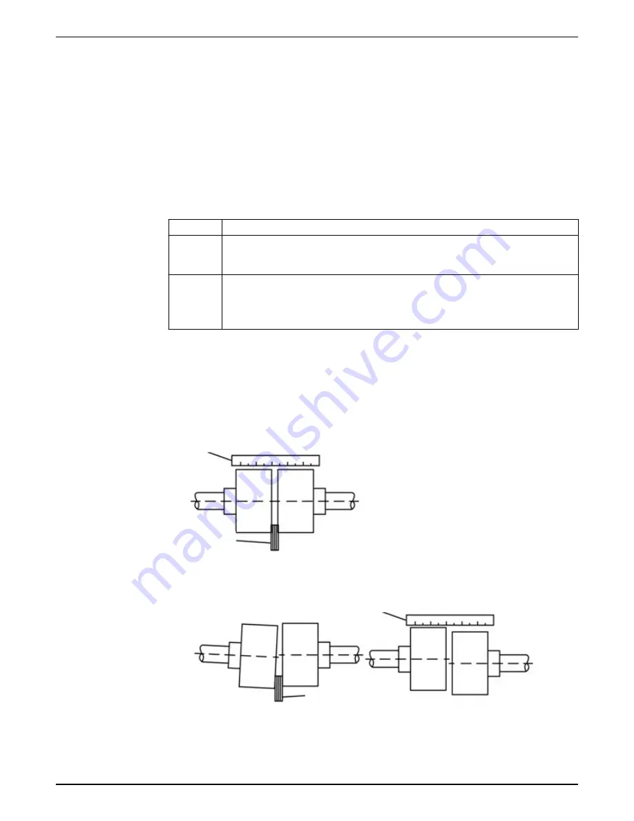
2. Check the parallel alignment:
a) Place a straight edge across the two coupler halves.
b) Measure the maximum offset at four points 90° apart. Do not rotate coupler.
c) Reposition the equipment until the gap is within the 1/64” permissible offset.
A coupling with a 3° angular misalignment will have a 0.191 in. (0.485 cm)
difference in measurements between L1 and L2. This is within the 0° to 4°
misalignment that is allowed for that size of coupling.
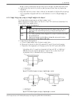
1
2
1. Straight edge
2. Feeler guage
Figure 4: Check the alignment using a straight edge - correct
1
2
Angular
Parallel
1. Straight edge
2. Feeler gauge
Figure 5: Check the alignment using a straight edge - incorrect
4 Installation
G&L Pumps Series A-C 8100 Base Mounted Centrifugal Pump INSTRUCTION MANUAL
17

