12
Verze 1 – GBR (11.3.2020)
D-502-0165
3.5.3.
Venting (discharge) valve
-
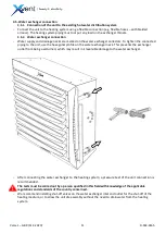
Water supply and drainage necks are marked on the water exchanger collectors. To tighten the connected
piping to the unit, use the hexagonal profile on the water exchanger neck. This prevents the exchanger
outlet from being overturned, which may result in irreversible damage to the water exchanger.
-
Drain the heating medium from the exchanger, by loosening the lower vent screw. If the unit is refilled with
a heating medium, check that the exchanger is vented.
-
Place the vent valves at the highest installation point.
3.5.4.
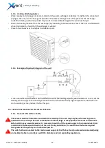
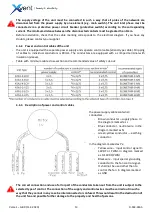
Example of hydraulic diagram of the unit
-
If the automatic control valve is not installed to control the heating capacity, we recommend to shut off the
heating water supply to the exchanger when the fan is switched off. Any high temperature inside the unit
on the exchanger may reduce the fan lifespan.
3.6.
Electrical installation and electrical connection
3.6.1.
General Information -Safety
-
The relevant electrical installation and electrical assembly of the units may only be performed by persons
qualified for this activity with valid authorization and knowledge of the applicable standards and directives.
Before starting any assembly works, it is necessary to switch off the power supply to the prepared electrical
installation for subsequent activation of the unit. During installation, the switch must be secured against
being switched on again by an unauthorized person.
-
The unit shall be connected to the main power supply by the TN-S system (neutral wire connected) using
an insulated cable in accordance with the diameter and corresponding regulations.

