


8
7
Manual - Mammoth
Troubleshooting
1
Machine Fails to
Start
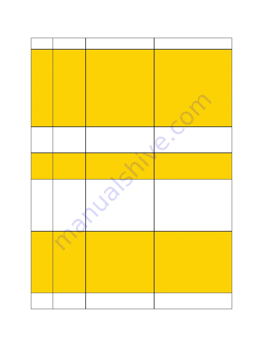
Trouble
No.
Abnormal
Phenomenon
1.improper line connection
2.Unmatched output voltage
3.Machine direction switch is broken
4. Machine speed-control switch is
broken
5.Machine emergency stop switch is
broken
6.Inverter is broken
7.Motor is broken
8. Air switch
9. The grinding plate is jammed by other
things
Cause
2
Fails to adjust
machine
frequency
1.Inverter parameters setup error
2.Speed-control potentiometer is broken
3.Short or open circuit of
connecting control line
3
Machine
Operation
noise
1.Motor or bearing is in an abnormal
phenomenon
2.lack of lubricants
3.Bearing or drive shaft is broken
4
Machine
operation
Migration
phenomenon
1. Move wheel and
grinding plates are not parallel
2.Three grinding plates are not
on the same level surface
3.Unmatched abrasive or different height
of abrasive tools
5
Machine
operation
dithering
phenomenon
1. move wheel and
grinding plates are not parallel
2.Three grinding plates are not
on the same level surface
3.Unmatched abrasive or
different height of abrasive tools
4.Gear box fixed bolt is loosing
6
Unusual LED
data
1.LED digital operator is
broken
1.Check line connection and power input termi-
nal; Make sure power output terminal no phase
open
2.Adjust to matched voltage that agrees with the
supplied machine voltage.
3.Replace broken direction switch
4. Replace broken speed-control switch
5. Replace broken emergency stop switch
6.Repair or replace inverter
7.Repair or replace motor
8. Input ampere should be at least 60A
9. Open the out cover of gear box and check if
there is other things
What To Do
1. Reset inverter parameters
2. Replace potentiometer
3. Replace control line
1.Replace motor or bearing
2.Add lubricants
3.Replace bearing or drive shaft
1.Adjust move wheel bolt to make sure the move
wheel keep the same force on the same flat
surface
2.Adjust grinding plates fixed bolt to make
sure all three grinding plates
on the same level surface
3.replace same specification and height
Abrasive tools
1.Adjust move wheel bolt to make sure the move
wheel keep the same force on the same flat
surface
2.Adjust grinding plates fixed bolt to make
sure all three grinding plates on the same level
surface
3.replace same
specification and height Abrasive tools
4.Tighten gear box fixed bolt to keep a
proper situation
1.Replace LED digital operator
2.Check and fix


