


Xtralis XAS-1-US Product Guide
Xtralis Pty Ltd
8. Do not position the probes next to outside air inlets unless you want to monitor smoke entry to the handling
system from an adjacent area.
9. Position the probes upstream of air humidifiers and cooling coils.
Notes:
l
The sample and exhaust tubes should be installed in a location of relatively non-turbulent air flow and within the
intended opening velocity range of 0-4000 feet per minute (0 to 1220 m/minute). It is recommended that
measurements of airflow and examination of engineering specifications that define expected duct air velocities
under all conditions and that measured velocities do not exceed the airspeed rating of the detector to be used.
This is done to determine if a location is suitable for duct sampling operation. An Alnor Instrument Co.
(Chicago) Model 6000P Velometer or equivalent (not supplied) may be used to check the duct air velocity.
l
The sampling and exhaust holes must be oriented facing out of the airflow. Refer to Section 3.3 on page 18 for
further information.
l
There must be at least 1 hole for every 1 foot of the inlet probe.
l
The inlet probe and outlet probe must have equal number of same diameter of holes in order to have a balanced
airflow in the pipe network.
l
Do not drill holes in the flexible tubes.
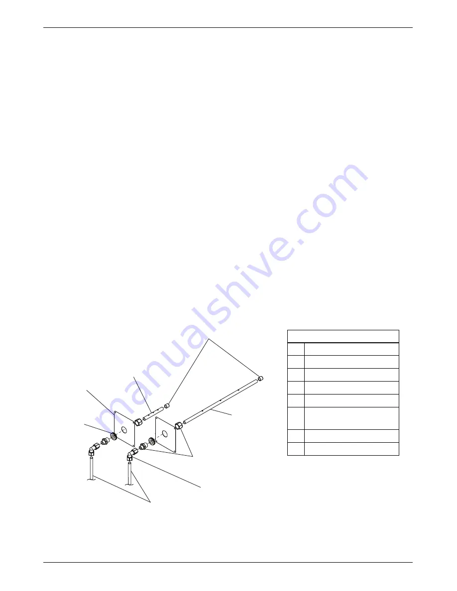
3.10.3 Duct Inlet Probe and Exhaust Pipe Installation
1. Mark the location of the mounting plates.
2. Drill or cut-out 2.0" in - 2.2" (50 mm - 55 mm) holes in the duct wall.
3. Cut the flexible tubes to the correct length. If longer than 3 feet, ensure the opposite end is supported on the
duct wall. This will maintain sample probe integrity across all duct air velocities.
4. Install the duct mounting plate - insuring that the plate covers the hole cut in duct in step 2 above.
5. Install the end caps to the inlet sampling probe and exhaust pipe.
6. Insert the sample probe through the compression fitting in the duct probe mounting plate.
7. Loosen the pipe compression adaptor coupling and insert the end of the sample tube. Tighten the compression
nut until the elbow is secure to the sample tube.
8. Repeat steps 2 thru 6 for the exhaust probe.
9. Insert the flexible tube to the elbow connector for the inlet and exhaust tubes. Tighten until the tube is secure.
C
E
F
D
A
B
G
H
Legend
A
Grommet
B
Mounting Plate
C
Exhaust Pipe
D
End Cap
E
Sampling Probe
F
Pipe Compression Adaptor
Coupling
G
Elbow Connector
H
Flexible Tubes
Figure 3-14: Duct inlet probe and exhaust pipe installation
30
www.xtralis.com


