


8
Power
-
External power adapter. Support DC 12V/AC 24V power supply.
PoE
-
Support Power over Ethernet (PoE). Conform to the IEEE802.3af
standard.
-
Connect the device to the switcher or the router that supports the PoE
function to realize the network power supply.
-
To guarantee proper performance, please make sure the power
sourcing device can supply at least 10W power.
The CCD series product
does not
support the PoE function.
Assistant
Function
-
Day/Night mode auto switch (
ICR switch.
)
-
Backlight compensation: screen auto split to realize backlight
compensation to adjust the bright.
-
Support system resource information and running status real-time
display. Support log function.
-
Support video watermark function to avoid vicious video modification.
1.3 Specifications
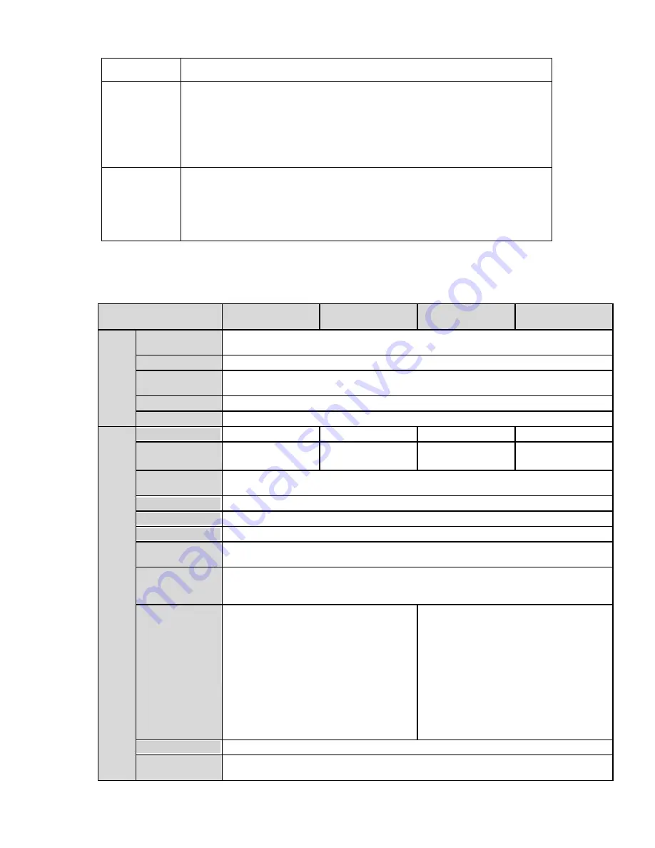
1.3.1 Performance
Please refer to the following sheet for IPC performance specification.
Model
Parameter
XL-ICA-106M3
XL-ICA-106M3W
CCD ver.
CCD ver.
S
yste
m
Main
Processor
TI Davinci high performance DSP
OS
Embedded LINUX
System
Resources
Support real-time network, local record, and remote operation at the same time.
User Interface
Remote operation interface such as WEB, DSS, PSS
System Status
SD card status, bit stream statistics, log ,software version ,online user
V
ide
o Par
amet
er
Image Sensor
1/2.8-inch CMOS
1/2.8-inch CMOS
1/3-inch CCD
1/3-inch CCD
Pixel
2048
(
H
)
*1536
(
V
)
2048
(
H
)
*1536
(
V
)
1280
(
H
)
*960
(
V
)
1280
(
H
)
*960
(
V
)
Day/Night
Mode
Support day/night mode switch and IR-CUT at the same time.
Auto Iris
Optional
Gain Control
Fixed/Auto
White Balance
Manual/Auto
Electronic
Shutter
Manual/Auto
(
It ranges from 1/50 to 1/10000
)
Video
Compression
Standard
H.264/JPEG
Video Frame
Rate
PAL:
Main stream
(
2048*1536@15fps
),
extra stream,
(
D1@12fps
)
Main stream
(
1920*1080@25fps
extra stream
(
D1@12fps
)
NTSC:
Main stream
(
2048*1536@15fps
extra stream
(
D1@12fps
)
Main stream
(
1920*1080@30fps
extra stream
(
D1@3fps
)
PAL:
Main stream
(
1280*960@12fps
),
extra stream,
(
D1@12fps
)
Main stream
(
1280*720@25fps
),
extra stream
(
D1@25fps
)
NTSC:
Main stream
(
1280*960@22fps
),
extra stream
(
D1@22fps
)
Main stream
(
1280*720@30fps
),
extra stream
(
D1@30fps
)
Video Bit Rate
160k~8Mbps. Support customized setup.
Video Flip
Does not support mirror.
Support flip function.
Summary of Contents for XL-ICA-106M3
Page 1: ...XL ICA 106M3 Megapixel Indoor User s manual...
Page 4: ...CD 1...
Page 21: ...21 Figure 2 5...


