background image

11 


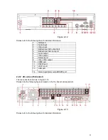
Figure 2-12 

Please refer to the following sheet for detailed information. 

GND port 

Audio input 

Video input 

Bidirectional talk output port 

Bidirectional talk input port 

Audio output 

Video output 

Network port 

Video VGA output 

10 

HDMI port 

11 

RS232 port 

12 

eSATA port 

13 

USB port 

14 

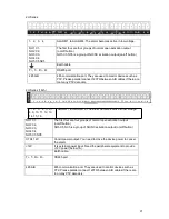
Alarm input/Alarm output/RS485 port 


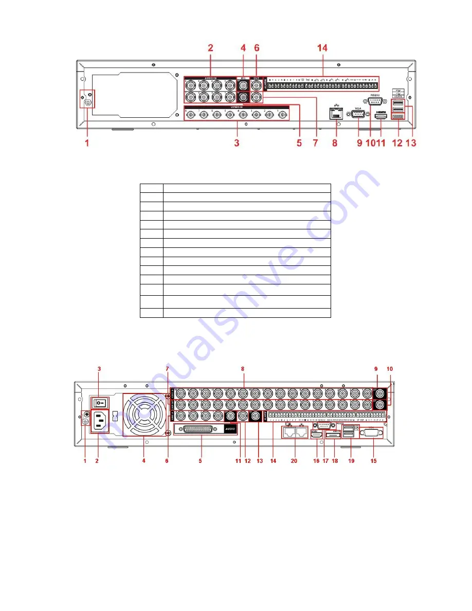
2.2.2  2U series (16channel)


The rear panel is shown as in Figure 2-13. 

Please note the following figure is based on the 16-channel series product. 


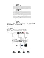
Figure 2-13 

Please refer to the following sheet for detailed information. 

Summary of Contents for H PG series

Page 1: ...DVR HxxPG PKC User s Manual...

Page 2: ...k Unpacked DVR 18 3 2 About Front Panel and Real Panel 18 3 3 HDD Installation 19 3 4 Rack Installation 20 3 5 Connecting Power Supply 20 3 6 Connecting Video Input and Output Devices 20 3 7 Connectin...

Page 3: ...TIONS AND CONTROLS 56 5 1 Menu Tree 56 5 2 Main Menu 56 5 3 Setting 57 5 4 Search 110 5 5 Advanced 110 5 6 Information 121 5 7 Shutdown 124 6 1 Go to Pan Tilt Zoom Menu 126 6 2 Preset Patrol Pattern B...

Page 4: ...nation and repair work should be done by the qualified service engineers We are not liable for any problems caused by unauthorized modifications or attempted repair 5 Environment The DVR should be ins...

Page 5: ...rrogation transportation intelligent resident zone factory warehouse resources and water conservancy 1 2 Features This series product has the following features Real time monitor It has analog output...

Page 6: ...can also connect to PC COM to upgrade system and realize maintenance and matrix control Standard Ethernet port can realize network access function Dual Ethernet ports support configuration modes such...

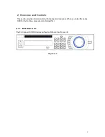
Page 7: ...provides information about front panel and rear panel When you install this series DVR for the first time please refer to this part first 2 1 1 DVR Hxx series The Front panel of HD SDI series is show...

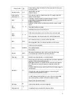
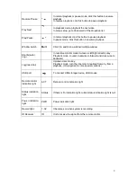
Page 8: ...e real time monitor mode Enter ENTER Confirm current operation Go to default button Go to menu Record REC Manually stop start recording working with direction keys or numeral keys to select the record...

Page 9: ...monitor mode it works as left right direction key Playback mode counter clockwise to forward and clock wise to backward Jog inner dial Up down direction key Playback mode turn the inner dial to realiz...

Page 10: ...ower input port 3 Power button 4 Fan 5 Video input 6 Loop video output 7 Audio input 8 Bidirectional talk input port 9 Bidirectional talk output port 10 Video output 11 Audio output 12 Alarm input Ala...

Page 11: ...ort 6 Audio output 7 Video output 8 Network port 9 Video VGA output 10 HDMI port 11 RS232 port 12 eSATA port 13 USB port 14 Alarm input Alarm output RS485 port 2 2 2 2U series 16channel The rear panel...

Page 12: ...talk output port 14 Alarm input Alarm output RS485 port 15 Video VGA output 16 HDMI port 17 RS 232 18 eSATA port 19 USB port 20 Network port When connect the Ethernet port please use crossover cable t...

Page 13: ...13 The 8 channel series product interface is shown as in Figure 2 18 Figure 2 18...

Page 14: ...14 2 3 4 2U series 960H series Please refer to the following figure for detailed information See Figure 2 19 The following figure is based on the 16 channel series product Figure 2 19...

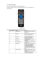
Page 15: ...can control it 3 Forward Various forward speeds and normal speed playback 4 Slow play Multiple slow play speeds or normal playback 5 Next record In playback mode playback the next video 6 Previous re...

Page 16: ...ltiple window switch Switch between multiple window and one window 14 Auxiliary key In 1 ch monitor mode pop up assistant function PTZ control and Video color Switch the PTZ control menu in PTZ contro...

Page 17: ...one item in the file list to playback the video In multiple window mode double left click one channel to view in full window Double left click current video again to go back to previous multiple windo...

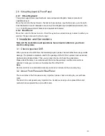
Page 18: ...form to your local electric safety rules 3 1 Check Unpacked DVR When you receive the DVR from the forwarding agent please check whether there is any visible damage The protective materials used for th...

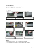
Page 19: ...ove the HDD upper bracket 3 Now you can see the bottom bracket 4 Line up the HDD to the four holes of the HDD bracket 5 Use screws to fix HDD 6 Install the upper bracket and then Use screws to fix HDD...

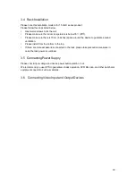
Page 20: ...d the device to guarantee sound ventilation Please install from the bottom to the top If there are more accessories connected in the rack please take precaution measures in case the rack power is over...

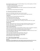
Page 21: ...wire should be fixed firmly and in well connection Avoid dry joint lap welding and oxidation BTTTB 3 6 2 Connecting Video Output Video output includes a BNC PAL NTSC1 0VP P 75 output a VGA output and...

Page 22: ...nected to high power load directly It shall be less than 1A to avoid high current which may result in relay damage Please use the co contactor to realize the connection between the alarm output port a...

Page 23: ...ries 16ch 1 2 3 4 5 6 7 8 9 10 11 12 13 14 15 16 ALARM 1 to ALARM 16 The alarm becomes active in low voltage NO1 C1 NO2 C2 NO3 C3 NO4 C4 NO5 C5 NC5 The first four are four groups of normal open activa...

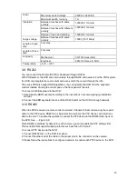
Page 24: ...connect the NC port of the alarm sensor to the DVR alarm input ALARM Use the same ground with that of DVR if you use external power to the alarm device 3 8 3 Alarm Output Port Provide power to periphe...

Page 25: ...ntrol pad on the front panel of the unit To connect a NKB keyboard to the DVR 1 Assemble the KBD keyboard according to the instructions in its accompanying installation manual 2 Connect the KBD keyboa...

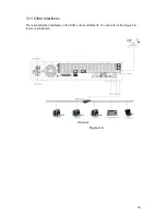
Page 26: ...26 3 11 Other Interfaces There are still other interfaces on the DVR such as USB ports You can refer to the Figure 3 6 for more information 2U Series Figure 3 6...

Page 27: ...utton you can go to the startup wizard interface Here you can set the system basic information See Figure 4 1 Figure 4 1 The system login interface is shown as in Figure 4 2 System consists of four ac...

Page 28: ...nced and shutdown You can move the cursor to highlight the icon and then double click mouse to enter the sub menu 4 1 3 Logout There are two ways for you to log out One is from menu option Figure 4 3...

Page 29: ...fy the channel name please refer to the display settings Main Menu Setting Display 1 Recording status 3 Video loss 2 Motion detection 4 Camera lock Preview Control The preview control function has the...

Page 30: ...lowing features Support play pause and exit and drag function During the preview playback process you can not see the channel title and record status of current channel It will display the channel tit...

Page 31: ...gure 4 7 Please check current channel status means it is not in recording status means it is in recording status You can use mouse or direction key to highlight channel number See Figure 4 8 4 3 4 Ena...

Page 32: ...have set in will be null Main menu Setting Schedule You can see indication light in front panel turns on system begins manual record now 4 3 5 Stop all channel recording Figure 4 10 Please highlight...

Page 33: ...re you can select to search the picture or the recorded file You can select to play from the read write HDD or the connected external device 3 Calendar The blue highlighted date means there is picture...

Page 34: ...at one time and can not lock the extra stream For the file that is writing or overwriting it can not be locked 6 Card number search The card number search interface is shown as below Here you can vie...

Page 35: ...The time bar zooms in the period of the current playback time when you are playing the file 10 Backup Select the file s you want to backup from the file list System max supports files from four channe...

Page 36: ...regular mode You can set record type and time in schedule interface 4 4 1 Schedule Menu In the main menu from setting to schedule you can go to schedule menu See Figure 4 14 Channel Please select the...

Page 37: ...p Copy function allows you to copy one channel setup to another After setting in channel 1 click Copy button you can go to interface Figure 4 16 You can see current channel name is grey such as channe...

Page 38: ...s old files once hard disk is full Please note only read write disk or read only disk can backup file and support file search function so you need to set at least one read write disk otherwise you can...

Page 39: ...e HD SDI series product supports 1080P 720P D1 HD1 2CIF CIF QCIF resolution The 960H supports 960H D1 HD1 2CIF CIF QCIF resolution In FTP Main Menu Network Network Setting interface please input uploa...

Page 40: ...the following figure for detailed information See Figure 4 19 Figure 4 19 4 5 2 3 Priority Please note the activation snapshot has the higher priority than schedule snapshot If you have enabled these...

Page 41: ...96 PAL 330 NTSC small zones The green zone is current cursor position Grey zone is the motion detection zone Black zone is the disarmed zone You can click Fn button to switch between the arm mode and...

Page 42: ...m occurs System one window tour Please go to chapter 5 3 9 Display for tour interval setup Snapshot You can enable this function to snapshoot image when alarm occurs Please highlight icon to select th...

Page 43: ...erface is shown as in Figure 4 26 This function allows you to be informed when video loss phenomenon occurred You can enable alarm output channel and then enable show message function Tips You can ena...

Page 44: ...deo continuity Camera masking interface is shown as in Figure 4 27 Tips You can enable preset tour pattern activation operation when video loss occurs Please refer to chapter 4 5 2 motion detection fo...

Page 45: ...el speed dome protocol and etc Select the channel of current speed dome as current monitor video and the right click mouse to select Pan Tilt Zoom item Now you can set preset tour pattern In Figure 4...

Page 46: ...arm MD Alarm Please note you can not select the MD Alarm and MD or Alarm at the same time Now you can go to the Encode interface to select the alarm record and set the encode parameter Main Menu Setti...

Page 47: ...47 Figure 4 28 Figure 4 29 Figure 4 30...

Page 48: ...includes USB burner flash disk SD card and portable HDD 4 8 1 Backup Figure 4 32 Select backup device and then set channel file start time and end time Click add button system begins search All match...

Page 49: ...skip the above three steps and then copy all the searched files directly The file name format usually is SN_CH channel number time Y M D H M S In the file name the YDM format is the same as you set i...

Page 50: ...setting and then click Pan Tilt Control button The interface is shown as in Figure 4 35 Here you can set the following items Channel select the current camera channel Protocol select corresponding PTZ...

Page 51: ...t zoom focus and iris Figure 4 37 In Figure 4 37 please click direction arrows See Figure 4 38 to adjust PTZ position There are total 8 direction arrows Figure 4 38 4 8 3 3D Intelligent Positioning Ke...

Page 52: ...unction Shortcut key Function key function Shortcut Key Zoom Near Far D Focus Near Far Iris close Open 4 10Preset Patrol Pattern Scan In Figure 4 37 please click the set button The interface is shown...

Page 53: ...In Figure 4 37 use eight direction arrows to adjust camera to the proper position In Figure 4 40 click preset button and input preset number The interface is shown as in Figure 4 42 Now you can add th...

Page 54: ...4 38 click border button The interface is shown as in X348H348H348H Figure 4 43 Please go to X349H349H349H X349H349H349HFigure 4 35 use direction arrows to select camera left limit Then please go to...

Page 55: ...55 Figure 4 46...

Page 56: ...Tilt Zoom Display Default Search Advanced Shutdown HDD Management Alarm Output Abnormity Manual Record Account Auto Maintain TV Adjust Video Matrix Title Overlay Config Backup 5 2 Main Menu After you...

Page 57: ...can see an interface is shown as in Figure 5 4 Here you can set start time and end time by setting corresponding week setup In Figure 5 4 enable date button you can see an interface is shown as in Fi...

Page 58: ...he box here system will go to the startup wizard directly when the system restarts the next time Otherwise it will go to the login interface Device ID Please input a corresponding device name here Rea...

Page 59: ...to 6 The sixth level has the highest image quality Video audio You can enable or disable the video audio Overlay Click overlay button you can see an interface is shown in Figure 5 7 Cover area Privac...

Page 60: ...you check the All box you set same encode setup for all channels Audio video enable box overlay button and the copy button is shield See Figure 5 9 Please highlight icon to select the corresponding fu...

Page 61: ...to the PC to transfer data directly Protocol COM is for card overlay function Network keyboard is for you to use the special keyboard to control the device PTZ matrix is to connect to the peripheral m...

Page 62: ...x shall have the same string DHCP It is to auto search IP When enable DHCP function you can not modify IP Subnet mask Gateway These values are from DHCP function If you have not enabled DHCP function...

Page 63: ...t be left in blank After completing all the setups please click save button system goes back to the previous menu Figure 5 11 Subnet Prefix Figure 5 12 5 3 5 1 Network Setting Network setting interfac...

Page 64: ...er you enabled this function only the IP listed below can access current DVR If you disable this function all IP addresses can access current DVR The system supports IPv4 and IPv6 address format Pleas...

Page 65: ...re 5 15 5 3 5 3 NTP Setup You need to install SNTP server Such as Absolute Time Server in your PC first In Windows XP OS you can use command net start w32time to boot up NTP service NTP setup interfac...

Page 66: ...r bit of the first byte 1110 Reserved local multiple cast group address 224 0 0 0 224 0 0 255 TTL 1 When sending out telegraph For example 224 1 1 1 All systems in the sub net 224 1 1 2 All routers in...

Page 67: ...r rebooting DVR will connect to internet automatically The IP in the PPPoE is the DVR dynamic value You can access this IP to visit the unit 5 3 5 6 DDNS Setup Figure 5 18 DDNS setup interface is show...

Page 68: ...in name and the IP address Right now current DDNS server is for our own devices only You need to refresh the bonding relationship of the domain and the IP regularly There is no user name password or t...

Page 69: ...n the LAN WAN IP It is the router IP in the WAN Port Mapping list The port mapping list here is the one to one relationship with the router s port mapping setting Enable Switch It shows that the funct...

Page 70: ...0 5 3 5 8 WIFI Setting Figure 5 21 You can view the WIFI connection status in the Network Setting interface See Figure 5 22 You can view current connection status and IP address if there is a connecti...

Page 71: ...mation such as the password if you have set it before Disconnect Here you can click it to turn off the connection Connect Here you can click it to connect to the hotspot System needs to turn off curre...

Page 72: ...WPA2 The display may become abnormal for the verification type and encryption type After device successfully connected to the WIFI you can view the hotspot name IP address subnet mask default gateway...

Page 73: ...is function and then set the corresponding interval System can send out the email regularly as you set here Click the Test button you can see the corresponding dialogue box to see the email connection...

Page 74: ...multiple folders under this FTP In Figure 5 209 select FTP and then double click mouse You can see the following interface See Figure 5 31 Please highlight the icon in front of Enable to activate FTP...

Page 75: ...ialogue box to see the FTP connection is OK or not See Figure 5 32 Figure 5 31 Figure 5 32 5 3 5 11 Alarm Centre This interface is reserved for you to develop 5 3 5 12 SNMP SNMP is an abbreviation of...

Page 76: ...anage in the MG SOFT MIB Browser Please set the corresponding version for your future reference Open the tree list on the MG SOFT MIB Browser you can get the device configuration Here you can see the...

Page 77: ...server when the device is online Important The server IP address can also be domain But you need to register a domain name before you run proxy device server 5 3 6 Alarm Please refer to chapter 4 6 Al...

Page 78: ...Resolution There are four options 1280 1024 default 1280 720 1024 768 800 600 Please note the system needs to reboot to activate current setup Image enhanced Check the box you can optimize the margin...

Page 79: ...eed to refresh web or client end to get the latest channel name System max support 25 digital character Figure 5 37 In tour mode you can see the following interface On the right corner right click mou...

Page 80: ...ease click save button system goes back to the previous menu Warning System menu color language time display mode video format IP address user account will not maintain previous setup after default op...

Page 81: ...shown as X Alarm set Click alarm set button the interface is shown as below See Figure 5 42 This interface is just like the abnormity setup Please refer to chapter 5 5 2 for detailed information HDD...

Page 82: ...ight corner of the Figure 5 41 system will pop up an interface as below See Figure 5 43 HDD Here you can view the HDD amount the device can support If there is a mark in the front of the number it mea...

Page 83: ...ng HDD group2 and set channel 2 and channel 4 to channel 16 to HDD group 1 In this setup the records from channel 1 and channel 3 are both saved in HDD of the group 2 The records from channel 2 and ch...

Page 84: ...e value ranges from 10s 300s System automatically delays specified seconds in turning off alarm and activated output after external alarm cancelled Show message system can pop up the message in the lo...

Page 85: ...tter number underline subtraction sign and dot System account adopts two level management group and user No limit to group or user amount For group or user management there are two levels admin and us...

Page 86: ...ight it can modify password of other users Figure 5 48 5 5 5 2 Add Modify Group Click add group button the interface is shown as below See Figure 5 49 Here you can input group name and then input some...

Page 87: ...r convenient user management usually we recommend the general user right is lower than the admin account The modify user interface is similar to Figure 5 50 Figure 5 50 5 5 6 Auto Maintain Here you ca...

Page 88: ...lease click OK button system goes back to the previous menu 5 5 8 Video Matrix Figure 5 52 Here you can set matrix output channel and its interval See Figure 5 53 It can support the 1 4 9 16 window sp...

Page 89: ...ay the card number Overlay mode There are two options preview and encode Preview means overlay the card number in the local monitor video Encode means overlay the card number in the record file Overla...

Page 90: ...total four groups IP The record channel applies to one group optional only Six frame ID groups verification can guarantee information validity and legal Figure 5 56 Click Data button you can see an i...

Page 91: ...remove the broken hard disk before you add a new one Once there is a hard disk confliction please check hard disk time and system time is the same or not Please go to setting then general to modify s...

Page 92: ...e Figure 5 61 Figure 5 61 5 6 3 Log Here is for you to view system log file System lists the following information See Figure 5 62 Log types include system operation configuration operation data manag...

Page 93: ...ailed information See Figure 5 63 5 6 4 Version Figure 5 63 Here is for you to view hardware features software version built date release SN information and etc You can also update system here See Fig...

Page 94: ...every five seconds to detect there is any newly added or deleted user Figure 5 65 5 7 Shutdown Double click shutdown button system pops up a dialogue box for you to select See Figure 5 66 Logout menu...

Page 95: ...125 Figure 5 66...

Page 96: ...Click Pan Tilt Zoom the interface is shown as in X398H398H398HFigure 6 2X Here you can set the following items Zoom Focus Iris Please click icon and to adjust zoom focus and Iris Figure 6 2 In X399H39...

Page 97: ...ce Figure 6 4 Name Function key function Shortcut key Function key function Shortcut key Zoom Near Far D Focus Near Far Iris close Open 6 2 Preset Patrol Pattern Border Function In X402H402H402HFigure...

Page 98: ...11H411H411HFigure 6 6X please input preset number in the No blank and click preset button 6 2 3 Patrol Setup In X412H412H412HFigure 6 5X click patrol button The interface is shown as in X413H413H413HF...

Page 99: ...hen please go to X423H423H423HFigure 6 10X and click left limit button Repeat the above procedures to set right limit 6 2 8 Activate Border Function Figure 6 10 In X424H424H424HFigure 6 6X click auto...

Page 100: ...130 Figure 6 11...
Page 101: ...l please run uninstall webrec2 0 bat Or you can go to C Program Files webrec to remove single folder Please note before you un install please close all web pages otherwise the un installation might re...

Page 102: ...n as below See X430H430H430HFigure 7 3X Please input your user name and password Default factory name is admin and password is admin Then you can select the login mode LAN and WAN Note For security re...

Page 103: ...buttons start dialog and local play refresh Section3 there are PTZ chapter 7 2 2 color chapter 7 2 3 button and you can also select picture path and record path Section 4 real time monitor window Plea...

Page 104: ...his series device does not support this function Figure 7 5 Section1 Section 3 Section 2 Section 4 Section 5 Figure 7 6 Real time Monitor In section 2 left click the channel name you want to view you...

Page 105: ...ghlighted You can go to system folder RecordDownload to view the recorded file 4 Capture picture You can snapshoot important video All images are memorized in system client folder download picture def...

Page 106: ...cess system will not encode the audio data from the 1 channel Local Play The Web can playback the saved Extension name is dav files in the PC end Click local play button system pops up the following i...

Page 107: ...sitioning key system goes back to the single screen mode Drag the mouse in the screen to adjust section size It can realize PTZ automatically 7 3 2 Speed System supports eight level speed You can sele...

Page 108: ...441H441HFigure 7 12X move the camera to your desired location and then input preset value Click add button you have set one preset 7 3 7 Auto tour In X442H442H442HFigure 7 12X input auto tour value an...

Page 109: ...htness contrast hue and saturation Current channel border becomes green Or you can click default button to use system default setup Figure 7 14 7 3 4 Picture Path and Record Path Click more button in...

Page 110: ...Figure 7 17X Please click choose button to modify path Figure 7 17 Click reboot button system pops up the following dialogue box See Figure 7 18 Please click OK to reboot Figure 7 18 If there is local...

Page 111: ...can select different channel and different monitor mode at the bottom of the interface See Figure 7 20 Figure 7 20 Important The window display mode and the channel number are by default For example f...

Page 112: ...u can see system close playback interface and open the configuration interface Please note system will not open the playback interface again after you close the configuration interface Figure 7 21 5 I...

Page 113: ...DD information Figure 7 22 Here you can view local storage status and network status including free capacity and total capacity See Figure 7 23 7 5 1 3 Log Figure 7 23 Here you can view system log See...

Page 114: ...event record operation user management log clear and file operation Search You can select log type from the drop down list and then click search button to view the list Start time Please input start...

Page 115: ...on to backup log files to current PC 7 5 2 System Configuration Please click save button to save your current setup 7 5 2 1 General Setup Here you can set system time record length video format and et...

Page 116: ...reboot to get the modification activated HDD Full There are two options stop recording or overwrite the previous files when HDD is full When current working HDD is overwriting or it is full now system...

Page 117: ...Stream It includes main stream motion stream and alarm stream You can select different encode frame rates form different recorded events System supports active control frame function ACF It allows yo...

Page 118: ...tem needs to low frame rate or video quality to guarantee the value The value is null in VBR mode Please refer to recommend bit rate for the detailed information Recommended Bit Recommended bit rate v...

Page 119: ...hen click save button Refresh Click this button to get device latest configuration information Click copy interface the interface is shown as in Figure 7 31 If you have completed the setup for channel...

Page 120: ...n data size Setup In Figure 7 32 click set button you can go to the corresponding setup interface See Figure 7 33 Please set schedule period and then select corresponding record or snapshot type sched...

Page 121: ...you complete setup for one channel or you can complete the whole setups and then click save button Refresh Click this button to get device latest configuration information n 7 5 2 4 RS232 The RS232 in...

Page 122: ...There are two options IPv4 and IPv6 Right now system supports these two IP address format and you can access via them MAC Address The host in the LAN can get a unique MAC address It is for you to acc...

Page 123: ...t device PPPoE Please input the PPPoE user name and password you get from the IPS internet service provider and enable PPPoE function Please save current setup and then reboot the device to get the se...

Page 124: ...digit Address Input receiver email address here Max input three addresses Support SSL TLS encryption mailbox Health mail enable Please check the box here to enable this function This function allows...

Page 125: ...ion Device IP is not fixed if you use ADSL to login the network The DDNS function allows you to access the DVR via the registered domain name Besides the general DDNS the private DDNS works with the d...

Page 126: ...mmonly used email address Important Do not register frequently The interval between two registrations shall be more than 60 seconds Too many registration requests may result in server attack System ma...

Page 127: ...ck save button after you complete setup for one channel or you can complete the whole setups and then click save button Refresh Click this button to get device latest configuration information NTP The...

Page 128: ...erface is shown as below See Figure 7 42 This interface is for you to develop The alarm signal can be uploaded to the alarm centre when there is local alarm Please set the corresponding parameters suc...

Page 129: ...of Simple Network Management Protocol It provides the basic network management frame of the network management system The SNMP widely used in many environments It is used in many network device softw...

Page 130: ...r detailed information Parameter Function Event Type It includes local alarm network alarm Local alarm Device detects alarm from input port Network Device detects alarm from network Alarm in Select co...

Page 131: ...record once alarm occurs working with alarm activation function Please note current device shall be in auto record mode Chapter 4 4 Schedule Record Latch System can delay the record for specified tim...

Page 132: ...arameter Function Event Type There are three types Motion detection video loss Camera Masking Channel Select channel name from the dropdown list Enable You need to draw a circle to enable motion detec...

Page 133: ...system can activate corresponding alarm device when alarm occurs Alarm latch System can delay the alarm output for specified time after alarm end The value ranges from 1s to 300s Show message System...

Page 134: ...click save button after you complete setup for one channel or you can complete the whole setups and then click save button Refresh Click this button to get device latest configuration information 7 5...

Page 135: ...can complete the whole setups and then click save button Refresh Click this button to get device latest configuration information 7 5 2 9 Default Backup Default Restore factory default setup You can...

Page 136: ...e the items on your right become valid You can check the corresponding item here See Figure 7 51 Figure 7 51 Please refer to the following sheet for detailed information Parameter Function Format Clea...

Page 137: ...Alarm output There are three output channels Multiple choices Please note the displayed alarm output channel amount here may vary due to the different series Activate Enable disable alarm output devi...

Page 138: ...up Manual Enable corresponding channel to record no matter what period applied in the record setup Stop Stop current channel record no matter what period applied in the record setup Operation here is...

Page 139: ...Auto Maintenance Figure 7 54 Here you can select auto reboot and auto delete old files interval from the dropdown list See Figure 7 55 7 5 3 6 Snapshot Figure 7 55 Snapshot interface is shown as in F...

Page 140: ...to 7f s Resolution You can select from the dropdown list The 1 Channel 1 and the 9 channel support D1 HD1 BCIF CIF QCIF Channel 2 to channel 8 channel 10 to channel 16 supports CIF QCIF Note 960H seri...

Page 141: ...alarm and corresponding activation output The value ranges from 10s to 300s Send email If you enable this function system can send out email to alarm the specified user Alarm upload System can upload...

Page 142: ...you can set preview mode 1 4 8 9 16 window The preview channel ranges from channel 1 to channel 16 See Figure 7 59 Figure 7 59 7 5 4 Additional Function 7 5 4 1 Preferred DNS Here you can set server o...

Page 143: ...host IP address that sends out information usually it is the device host connected to the DVR Destination IP refers to other systems that receive information There are total four groups IP The record...

Page 144: ...Enable Enable auto register function No Device management server number IP Device management server IP address Port Server port number Device ID Device ID in the device management server 7 5 4 4 Mobi...

Page 145: ...WIFI interface is shown as in Figure 7 64 Here you can view WIFI connection status System displays as no connection if there is no connection You can view connection status and IP address if there is...

Page 146: ...tion status You can view connection status and IP address if there is a connection Otherwise system shown as there is no hotspot connection 7 6 Search Click search button you can see an interface is s...

Page 147: ...to download and then click download button system pops up a dialogue box shown as in X480H480H480HFigure 7 62 then you can specify file name and path to download the file s to your local pc Figure 7 6...

Page 148: ...lows you to backup the record or picture to your local USB storage media via the Web remotely Click the search button you can view the available storage device See Figure 7 69 Please select from the d...

Page 149: ...Operation Listen alarm System notifies web when alarm occurs you select from the above event type and then web can notify user Now you can see system begins download and the download button becomes s...

Page 150: ...s up alarm dialogue box Sound pop up System sends out alarm sound when alarm occurs You can specify as you wish Path Here you can specify alarm sound file 7 8 About Click about button you can view cur...

Reviews: