XtendLan DPC-D250 series User Manual Download Page 13

-13-

Setting Image Display Mode

Please know that this setting is only effective for monitors which does not support man-
ual operation for pan-tilt. 

When door station calls monitor,the image will be displayed on screen,there are 3 modes for im-
age displayed, 

Alternate switching mode

,

Zoom mode 

and

 Full screen mode

.  

Alternate switching mode: 

when the monitor being called, switch at regular time(5s) between 

Full screen

 and 

Zoom

 image.

Zoom mode: 

when the monitor being called, the image will be displayed on full screen for 5 

seconds, then switch to 

Zoom

 image. 

Full screen mode: 

when the monitor being called, the image will be always displayed on 

Full 

screen

.

Alternate switching mode is default, to change the setting, please follow the steps:

When answering the call, the image switching reminder can be activated or forbidden. 
If set to activated mode, the image switching reminder will be different for different image display 
mode.

Alternate switching mode: 

When answering the call, image switching reminder is not effective.

Zoom mode: 

When answering the call, the image will be displayed on 

full screen

 for 5 sec-

onds, then switch to 

Zoom

 image to remind to enter talking status. 

UNLOCK Indicator:ON
TALK Indicator:ON

Buzzer

Beep+, Beep

In standby mode, press 

KEY_SET

 button 

four 

times

.

UNLOCK Indicator:ON
TALK Indicator:ON

Buzzer

Beep+

Press 

KEY_2 

button to set 

the image display mode 

to

 Cycle switching

.

UNLOCK Indicator:ON
TALK Indicator:ON

Buzzer

Beep, Beep

Press 

KEY_2 

button again

to set the image display 

mode to

 Zoom mode

.

UNLOCK Indicator:ON
TALK Indicator:ON

Press 

KEY_2

Buzzer

Beep, Beep,Beep

Press 

KEY_2 

button again

and again to set the image 

display mode to

 Full screen

.

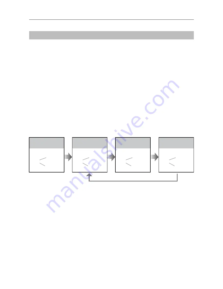
During setting mode, press 

KEY-2

 to switch


Cycle switching 

mode

Zoom 

mode and 

Full screen

 mode in cycle.

SETUP INSTRUCTIONS

When the monitor being called

When answering the call

• 

If setting mode has not been exited, you can change the image display mode by pressing KEY2 circularly.

• 

The 

LED_NAME

 indicator will blink all the time until exit out the setting mode.

• 

If without any operation in 10 seconds, it will exit out setting mode automatically.

• 

In this step,press 

KEY_SET

 button once to exit out the setting mode manually.

Summary of Contents for DPC-D250 series

Page 1: ...250 series A door station with proximity access control USERMANUAL RF CARD RF CARD RF CARD RF CARD RF CARD RF CARD Please read this manual carefully to ensure safe and correct operation Keep this manu...

Page 2: ...de 8 Setting Camera Resolution 10 Setting Unlock Mode 10 Setting Unlock Time 11 Setting Nameplate Illumination Mode 11 Setting Night View LED Illumination Mode 12 Setting Ring back Tone 12 Setting Ima...

Page 3: ...8 7 6 5 12 11 12 13 13 2 2 Surface mounted Flush mounted 1 Microphone 2 UNLOCK indicator 3 CALL indicator 4 Call button 5 Nameplate 6 Front panel 7 Speaker 8 Night view LED 9 Camera lens 10 Rainy cove...

Page 4: ...ate 4 Attach the front panel to the main unit 5 Use the special screwdriver and the screws to fix the panel 1 Drill a hole in the wall to match the size of mounting box then attach the mounting box to...

Page 5: ...ocks L1 L2 Connect to the bus line no polarity PL External lock power input connect to the power positive power S Lock power output S Lock power output connect to the power input of locks only when us...

Page 6: ...quires the monitor with fisheye function to support The angle view is 1700 visitors in this angle view can be seen clearly and can be zoomed to see individuals up close via indoor monitor with fisheye...

Page 7: ...Order Setting items Setting range Default value 1 Setting door station address 0 3 0 2 Setting door station calling mode Standard Group calling mode Standard calling mode 3 Setting camera resolution...

Page 8: ...FF TALK Indicator OFF Buzzer Beep Beep UNLOCK Indicator OFF TALK Indicator OFF Buzzer Beep Beep Beep UNLOCK Indicator OFF TALK Indicator OFF Buzzer Beep Beep Beep Beep ID 0 1st door station ID 1 2nd d...

Page 9: ...address 02 by default Call buttonC call the monitor with address 03 by default Call buttonD call the monitor with address 04 by default Call buttonA Call all monitors in group address from 00 15 one...

Page 10: ...ode press KEY_SET button three times UNLOCK Indicator ON TALK Indicator OFF Buzzer Beep Press KEY_1 button to set the unlock mode to Normally opened UNLOCK Indicator ON TALK Indicator OFF Buzzer Beep...

Page 11: ...ion mode to Normally on UNLOCK Indicator ON TALK Indicator OFF Buzzer Beep Beep Press KEY_3 button again to set the nameplate illumina tion mode to Normally off UNLOCK Indicator ON TALK Indicator OFF...

Page 12: ...Auto Press KEY_4 UNLOCK Indicator ON TALK Indicator ON Buzzer Beep Beep In standby mode press KEY_SET button four times UNLOCK Indicator ON TALK Indicator ON Buzzer Beep Press KEY_1 button to set the...

Page 13: ...swering the call image switching reminder is not effective Zoom mode When answering the call the image will be displayed on full screen for 5 sec onds then switch to Zoom image to remind to enter talk...

Page 14: ...Hz Authorizing master cards By default there are two master cards marked MASTER CARD ADD and MASTER CARD DELETE but you should know that the master card can be authorized by users at any time That mea...

Page 15: ...t out setting mode automatically If current access is controlled by door station next access switching setting is controlled by ACC UNLOCK Indicator Blink two times TALK Indicator OFF Buzzer Beep Beep...

Page 16: ...equence UNLOCK Indicator OFF TALK Indicator OFF Buzzer Beep Beep Show the master card of MASTER CARD DELETE again to exit UNLOCK Indicator ON TALK Indicator OFF Buzzer Beep Beep Show the master card o...

Page 17: ...om Exit Button EB 5 The Unlock Mode must be set to 0 by default 1 The external power supply must be used according to the lock 2 The inside relay contact is restricted to 230Vac 1A or 24Vdc 1A 3 The j...

Page 18: ...on 1 2 3 4 5 6 ON DIP L2 L1 DIP Switches RF CARD PC6A AC 100 240VAC 100 240VAC DBC4A1 A B C D OFF ON Impedance switch BUS IM BUS DS PC6A AC ID 0 1st door station ID 1 2nd door station ID 2 3rd door st...

Page 19: ...fer to Page 9 Distributor is unnecessary in full audio system and IN OUT mode is recom mended For the last monitor connected to the system DIP6 should set to ON ID 0 Code 1 DIP6 off Optional functiona...

Page 20: ...stributor for the extension WIRING DBC4A1 A B C D RLC DBC4A1 OFF ON Impedance switch BUS IM BUS DS Code 1 DIP6 on Code 2 DIP6 on Code 3 DIP6 on Code 4 DIP6 on ID 0 RF CARD PC6A AC 100 240VAC Optional...

Page 21: ...acture Pay attention to the high voltage inside the products please refer service only to a trained and qualified professional APPENDIX Power supply DC 24V Power consumption Standby 0 8W Working 3W Ca...

Page 22: ...s limited in the system Using different cables may also affect the maximum distance which the system can reach Cable and distance unit m Cable Usage A B 2 IM B 16 IM Twisted cable 2x0 75mm2 60 100 40...

Page 23: ...23 B A C 2 2 DBC4A1 RF CARD PC6A Cable and distance unit m Cable Usage A B C Twisted cable 2x0 75mm2 60 60 30 Twisted cable 2x1mm2 80 80 40 APPENDIX Star Topology Wiring Mode With DBC4A1...

Reviews: