-5-
RF CARD
BUS(IM) BUS(DS)
PC6
AC~
BUS(OUT) BUS(IN)
QSW
1# Camera
2# Camera
4# Camera
3# Camera
1
2
3
4
5
6
ON
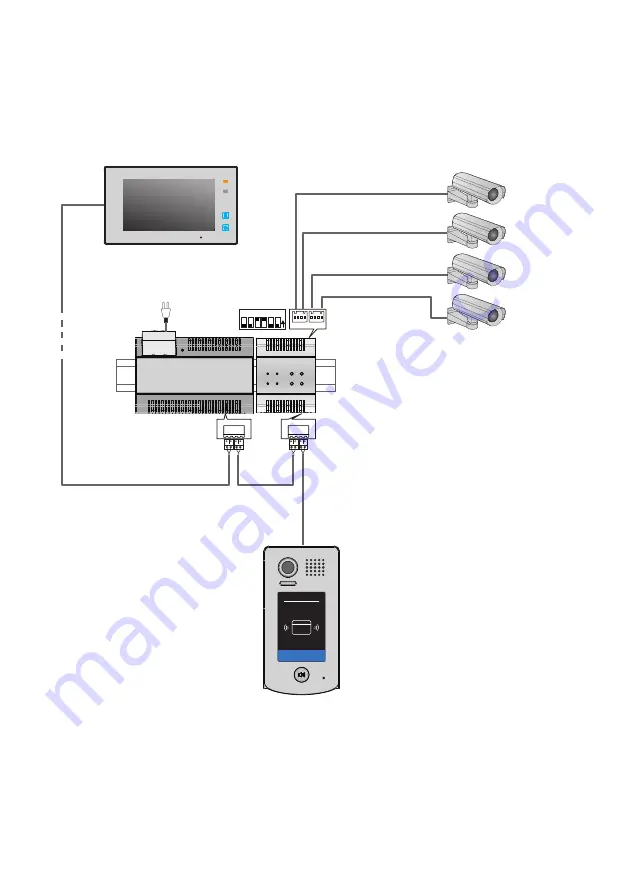
4. Wiring Diagram
4.1 Single door station and single QSW applications:
Page 1: ...DPA D2 QSW a video quad splitter User manual...
Page 2: ...QSW module is designed to 2D system for the purpose of video quad splitter four images from 4 different cameras can be displayed on screen of monitor via QSW unit NOTE For monitor which support split...
Page 3: ...en CAM4 video output CAM 1 4 indicator flash when video split output video BUTTONS 1 Press CAM1 button in monitoring state the system will mandatory output the video of CAMERA 1 2 Press CAM2 button in...
Page 4: ...amera unavailable When set to ON it means that the fourth camera available 1 2 3 4 5 6 ON 1 2 3 4 5 6 ON 1 2 3 4 5 6 ON set to the second QSW set to the third QSW set to the fourthQSW When set to OFF...
Page 5: ...4 3 Unit Mounting Din rail Din rail Mounting Buckle Step1 Mount the din rail to the wall with screws Step2 Pull down the mounting buckle then hang the unit on din rail...
Page 6: ...5 RF CARD BUS IM BUS DS PC6 AC BUS OUT BUS IN QSW 1 Camera 2 Camera 4 Camera 3 Camera 1 2 3 4 5 6 ON 4 Wiring Diagram 4 1 Single door station and single QSW applications...
Page 7: ...OUT BUS IN QSW DBC 4A A B C D RF CARD Device Address 1 Device Address 0 QSW a b 1 Camera 2 Camera 4 Camera 3 Camera 5 Camera 6 Camera 8 Camera 7 Camera 1 2 3 4 5 6 ON BUS OUT BUS IN 1 2 3 4 5 6 ON NOT...
Page 8: ...5 Specification Power Supply DC24V Working Temperature 150 C 550 C Wiring 2 wire non polarity Dimension 90 H 72 W 60 D mm DPA D2 QSW...