

WARNING! Verify that there is clearance before drilling the holes for the LED's and keep the harness away from any
hot or moving parts.
2.
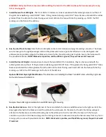
Install the two front LED lights -
The front LED Turn Indicators can be mounted with the rubber grommet or without. If
the grommet is
not
being used drill 5/8” holes. If the grommet is being used drill ¾” holes. Remove and install the rubber
grommet from the LED into the hole if being used. Insert LED into the hole with the Top marking up. NOTE: the TOP
marking is on the front of the LED lens.
3.
Run the short front harness
from the front LED lights to the control module and plug into mating connector. The Green
wire harness go to the right/passenger side and the yellow wire harness go to the left/
driver’s
side. Both green and
yellow wires are positive and go to the black wire on each side, the white wire goes to white. Secure the harness with
the provided cable ties.
NOTE: Black wire is positive, and the White is ground, they will not work if reversed.
4.
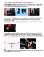
Install the Rear LED Lights-
Decide where to mount the two RED LED Turn Indicators, they can be mounted with the
rubber grommet or without. If the grommet is
not
being used drill 5/8” holes. If the grommet is being used drill ¾” holes.
Remove and install the rubber grommet from the LED into the hole if being used. Insert LED into the hole with the Top
marking up. NOTE: the TOP marking is on the front of the LED lens.
Optional RZR Old Style Light Modification:
The directions on installing the Rear Turn LED
’s into a Factory Light can
be found at www.xtcinstall.com.
Sample: Rear LED Lights installed into an OEM rear Light Housing
5.
Run the Rear Harness -
Start at the right rear of the car and attach the Green and White wires to the right rear LED, the
Green gets attached to the black wire and the white to the white wire. Do the same for the left, the Yellow wire gets
attached to the black wire and the white wire goes to the white wire. Run the rest of the harness with the four-pin
connector up to the control box and plug into the mating connector, make sure to keep the harness away from any hot or
moving parts, secure with provided cable ties.
NOTE: Black wire is positive, and the White is ground, they will not work
if reversed.