background image

 
 EXEMPTIONS 


We are not liable for: 
1.  Damage caused  by  fires,  natural  disaster  (such  as  thunder,  earthquake,  etc.),  acts 

by third party, accidents, misuse, or use in other improper conditions. 

2.  Incidental  damages  (such  as  profit  loss  or  interruption  to  business,  modification  or 

erasure of data and so forth) caused by use or inability to use of this product. 

3.  Damage caused by neglect of instructions as described in the operating manual. 
4.  Damage caused by misuse or malfunction through simultaneous use of this product 

and other connected equipment. 

 
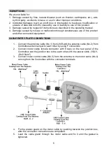
CABLE ENTRY PLATE CONNECTIONS 
 

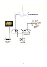
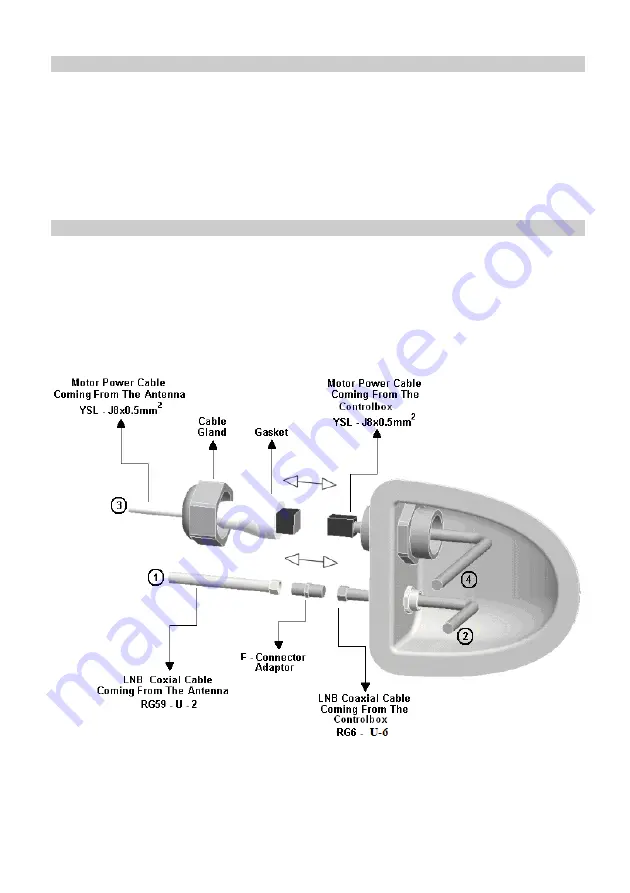
1.  Connect the antenna cable (No.1) from LNB and the antenna cable (No.2) from 

Controlbox antenna input to each other by using F connectors. 

2.  Connect  motor  cable  female  connector  with  8  taps  on  the  rear  panel  of  the 

Controlbox and the junction box to the each other with the power cable. (YSLY-
J 8x0.5mm²) 

3.  Connect motor control cable (No.3) from the antenna to the motor cable (No.4) 

coming from the Controlbox with the connector terminals. 


4.  Fix  the  plastic  guard  on  the motor cable  by  pushing  towards  the junction  box, 

after the connector connections are completed. 

5.  Lead  the  cable  gland  through  the  motor  cable  and  fix  it  until  the  gasket  is 

tightened. 


Summary of Contents for MTA 50

Page 1: ...MTA 50 MTA 65 Serie MTA 80 Serie INSTALLATION MANUEL...

Page 2: ...1...

Page 3: ...E OF CONTENTS Page GENERAL 3 IMPORTANT SAFETY INSTRUCTIONS 3 PACKING LIST 4 USAGE 4 EXEMPTIONS 5 CABLE ENTRY PLATE CONNECTIONS 5 INSTALLATION MANUAL 6 THE CASES THAT SHOULD BE CONSIDERED 6 INSTALLATIO...

Page 4: ...cause damage to the vehicle as well as it will be dangerous for life safety The system shuts down itself and closes the antenna automatically when the vehicle is operated but checking on whether the...

Page 5: ...the satellite is found the signal will be available on the receiver which is connected to the loop out port of Controlbox and the channels on the receiver can be watched Turn off the system To turn of...

Page 6: ...ct and other connected equipment CABLE ENTRY PLATE CONNECTIONS 1 Connect the antenna cable No 1 from LNB and the antenna cable No 2 from Controlbox antenna input to each other by using F connectors 2...

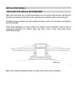
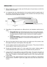
Page 7: ...tallation place of the antenna Installation place should be smooth and plain surface and on the centerline according to the vehicle width While doing installation at rough surfaces the bottoms of the...

Page 8: ...ording the adhesive Fix the motor unit by bonding it to the mounting surface 4 Stick the foam band 40cm far away from the rear middle axis of the antenna after thoroughly cleaning the mounting area of...

Page 9: ......

Page 10: ...9...

Page 11: ......

Page 12: ......

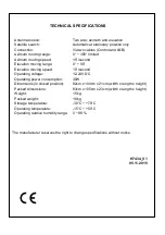
Page 13: ...0 Elevation moving speed 10 second Operating voltage 12 24V DC Operating power consumption 30W Dimensions in closed position 82cm x 104cm x 21cm width x length x height Packed dimensions 83cm x 105cm...

Reviews: