19
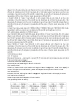
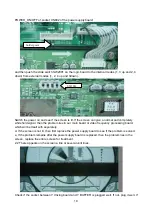
POWER_ON/OFF of socket CN802 of the power supply board;
and then push the slide switch SW2001 on the logic board to the internal modes (1, 3 up and 2, 4
down) from external modes (1, 2, 4 up and 3down).
Switch the power on and see if the screen is lit. If the screen can give a normal and completely
white field signal, then the problem lies in our main board or video frequency processing board,
which will be dealt with separately.
d. If the screen is not lit, then first replace the power supply board to see if the problem is solved.
e. If the problem remains after the power supply board is replaced, then the problem lies in the
screen, replace the entire screen for treatment.
2.2 There appears on the screen a line or several unlit lines.
Check if the socket between Y driving board and Y BUFFER is plugged well. If not, plug it well. If
Solder point
SW2001
Summary of Contents for PH42T7
Page 1: ...PDP TELEVISION PH42T7 ...
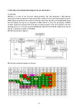
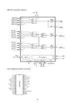
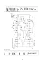
Page 17: ...15 M52797 Internal block diagram The arrangement diagram of the pins ...
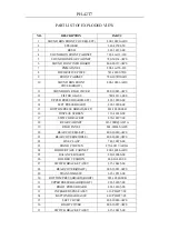
Page 30: ...EXPLODED VIEW ...
Page 58: ......
Page 59: ......
Page 60: ......
Page 61: ......
Page 62: ......
Page 63: ......
Page 64: ......
Page 65: ......
Page 66: ......
Page 67: ......


