


17
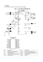
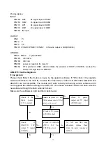
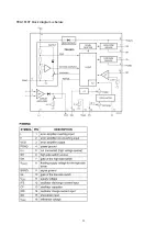
Pin description:
INPUT:
PIN162 DP2 D+ signal input of USB2
PIN163 DM2 D- signal input of USB2
PIN173 DP1 D+ signal input of USB1
PIN174 DM1 D+ signal input of USB1
PIN189 IR input
OUTPUT:
PIN9 Pr
PIN12 Y
PIN15 Pb
PIN197 / PIN200 / PIN201 / PIN202 I2S audio output to NU8(CS4334)
OTHERS:
PIN51 / PIN52 crystal 27MHz
PIN185 I2C DATA
PIN186 I2C CLK
PIN208 power on reset pin for main IC
PIN168 OTG symbol of USB1, which indicate the situation of HOST or DEVICE, low level for
HOST and high level for DEVICE.
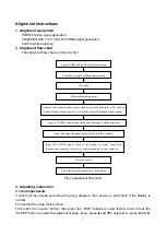
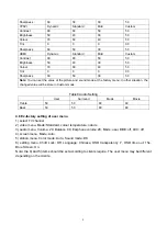
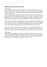
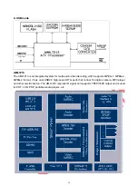
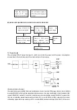
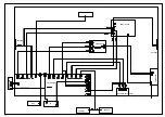
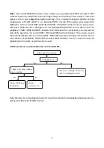
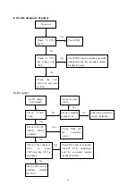
AML7213 trouble diagnosis
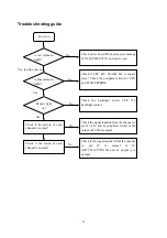
(1) no picture:
Please check firstly if the trouble is cause by the upgrade software, if YES, check if the upgrade
software matches to the main IC, because the three kinds of versions of AML3428, AML3278 and
AML7213 are not compatible. The module can’t work correctly with wrong version software and it
can’t upgrade the software through the USB port. You should unsolder FLASH and flash write the
new software through the flash write instrument.
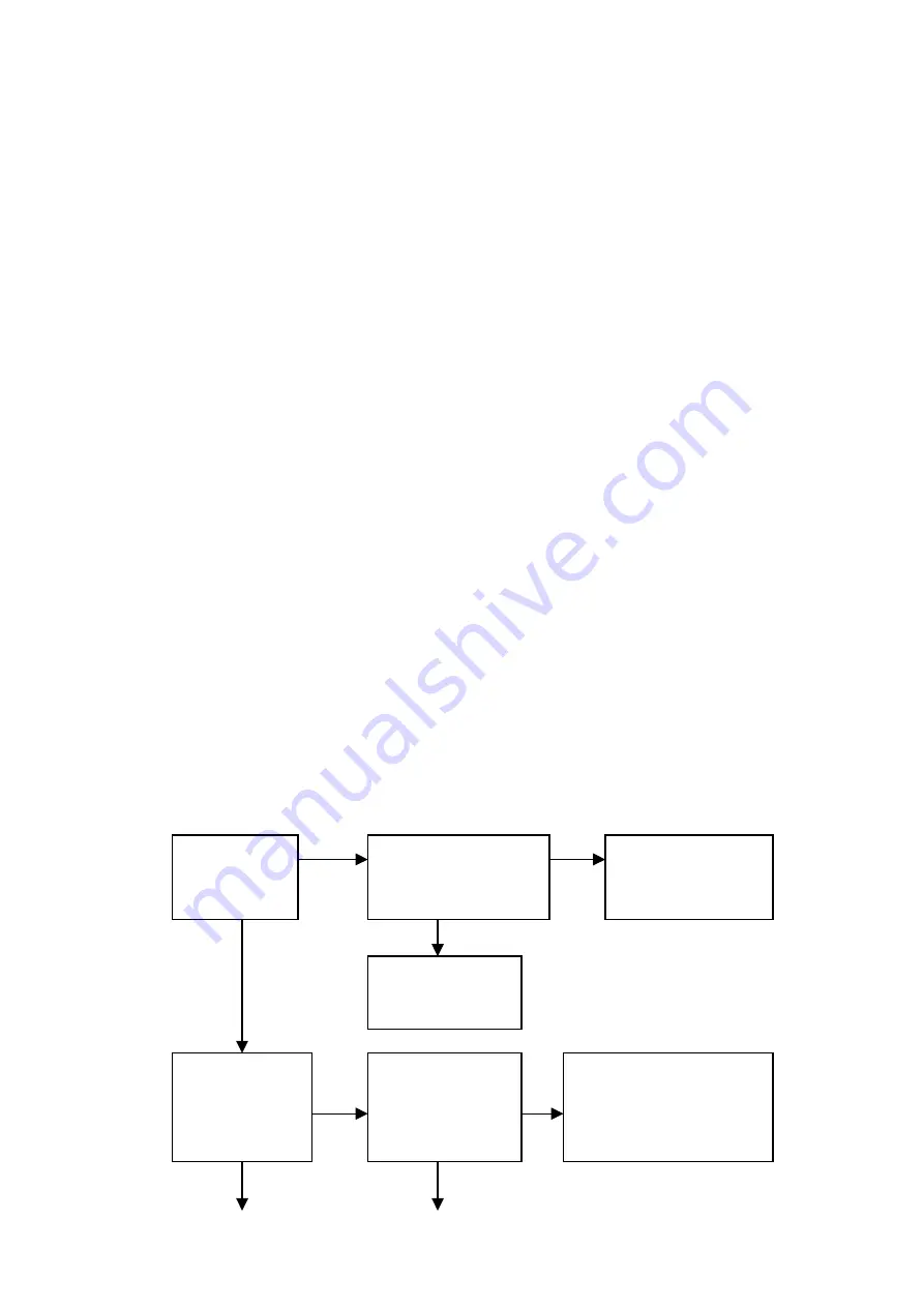
Make sure the software is right and then check below:
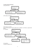
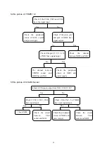
Check if the
input power
(5V) is normal
Remove the power (5V) from
USB board and check if 5V of
output port is normal
Check 5V power
output and 5V input
of USB board
Check if 5V power
of USB is short
Check if
AML7213 12#
output Y signal
normally
Check if SDRAM
(NU3) 38# has
108M sine wave
N1, NU3 and NU4 may
abnormal, replace them
when the power supply is
normal
No
No
No
No
Yes
Yes
Yes Yes
Summary of Contents for LC-42HW36
Page 1: ...LCD TELEVISION LC 42 47HW36 ...
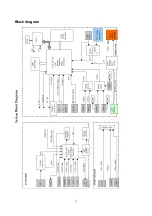
Page 14: ...12 Block diagram ...
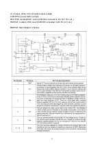
Page 22: ...20 L6563 block diagram is below ...
Page 23: ...21 ...
Page 24: ...22 TEA1610T block diagram is below ...
Page 34: ......
Page 35: ......
Page 36: ......
Page 37: ......
Page 38: ......
Page 39: ......
Page 40: ......
Page 41: ......
Page 42: ......
Page 43: ......
Page 44: ......
Page 45: ......
Page 46: ......
Page 47: ......
Page 49: ...APPENDIX Exploded view LC 42X36 ...
Page 51: ...APPENDIX B Exploded view LC 47X36 ...
Page 53: ...9242HW3614 Ver 1 0 ...


