background image

- 14 -

4.  INSTALL THE DUCT COVER:

Arrange the electrical power supply within the dimensions of the decorative flue. If your 
appliance is to be installed in the ducting version or in the version with external motor, 
prepare the air exhaust opening. Adjust the width of the support bracket of the upper 
flue 

(Fig.7)

. Then fix it to the ceiling using the screws 

A


(Fig.7)

 in such a way that it is 

in line with your hood and respecting the distance from the ceiling indicated in 

Fig.6

Connect the flange 

C

 to the air exhaust hole using a connection pipe 

(Fig.8)

. Insert the 

upper flue into the lower flue. Fix the lower flue to the hood using the screws 

B

 provided 

(Fig.8)

, extract the upper flue up to the bracket and fix it with the screws 

B


(Fig.7)

.

B

C

:.205#

609#

B

D

B

Fig.6

Fig.7

Fig.8

Summary of Contents for XOR24S

Page 1: ...anual de utilización USA F E XOR24S XOR30S XOR36S NEED HELP Call our ventilation experts toll free al 800 966 8300 AVEZ VOUS BESOIN D AIDE Contactez nos experts au numéro gratuit 800 966 8300 NECESITA AYUDA Póngase en contacto con nuestros expertos a través del número gratis 800 966 8300 ...

Page 2: ...iginal purchaser for products purchased for ordinary home use in North America Should you require service for your XO product call a product service specialist at 800 966 8300 Improper Installation Service trips to the home to teach you how to use the product Resetting circuit breakers Damage caused after delivery EXPECT MORE FROM XO When buying any XO appliance you can be confident you have purch...

Page 3: ...s and vapors CAUTION To avoid motor bearing damage and noisy and or unbalanced impellers keep drywall spray construction dust etc off power unit CAUTION Please read specification label on product for further information and requirements WARNING TO REDUCETHE RISK OF FIRE ELECTRIC SHOCK OR INJURYTO PERSONS OBSERVE THE FOLLOWING A Use this unit only in the manner intended by the manufacturer If you h...

Page 4: ...inguisher ONLY if 1 You know you have a Class ABC extinguisher and you already know how to operate it 2 The fire is small and contained in the area where it started 3 The fire department is being called 4 You can fight the fire with your back to an exit aBased on kitchen firesafety tips published by NFPA Proper maintenance of the Range Hood will assure proper performance of the unit INSTALLATION I...

Page 5: ...s after a prolonged use of the appliance C No food must be cooked flambè underneath the hood D The use of an unprotected flame is dangerous for the filters and could cause fires E Watch constantly the fried food in order to avoid the cooking oil flares up F Before performing any mainteinance operation disconnect the hood from the elec trical service The manufacturers will not to accept any respons...

Page 6: ...terruption of such naturally vented systems follow the heating equipment manu facturer s guidelines and safety standards such as those published by NFPA Duct Piece Dimensions Equivalent Number Length Quantity Used Total Equivalent Length Round straight 1 ft per foot lenhgth 3 1 4 x 10 straight 1 ft per foot lenhgth 90 elbow 12 ft 45 elbow 7 ft 3 1 4 x 10 3 1 4 x 12 90 elbow 14 ft 10 ft 3 1 4 x 10 ...

Page 7: ...pe or Duct Tape INSTALL THE DUCTWORK NOTE To reduce the risk of fire use only metal ductwork 1 Decide where the ductwork will run between the hood and the outside 2 A straight short duct run will allow the hood to perform most efficiently 3 Long duct runs elbows and transitions will reduce the performance of the hood Use as few of them as possible 4 Install a roof or wall cap Connect 6 round metal...

Page 8: ... 41 47 Ù7 4 22027 2 22027 35 31 809 41 47 22 205 21 2027 4 209 37 Nby 56 2027 Njo Fyusbdups 38 4027 Njo Gjmufsjoh 42 6027 Front of hood Side of hood Top of hood Mounting height and clearance PRODUCT DIMENSIONS AND CLEARANCE XOR24S XOR30S XOR36S ...

Page 9: ...he appliance has been adjusted definitely fix the hood using the screws A Fig 2 For the vari ous installations use screws and screw anchors suited to the type of wall e g reinforced concrete plasterboard etc If the screws and screw anchors are pro vided with the product check that they are suitable for the type of wall on which the hood is to be fixed IMPORTANT The range hood must be secured to wa...

Page 10: ...TU CF XJSF XJUI HSPVOE t G UIF FMFDUSJDBM TVQQMZ EPFT OPU NFFU UIF BCPWF SFRVJSFNFOUT DBMM B MJDFOTFE electrician before proceeding t 3PVUF IPVTF XJSJOH BT DMPTF UP UIF JOTUBMMBUJPO MPDBUJPO BT QPTTJCMF JO UIF DFJMJOH PS back wall Refer to Wiring Locations on page 11 t POOFDU UIF IPPE XJSJOH UP UIF IPVTF XJSJOH JO BDDPSEBODF XJUI MPDBM DPEFT Grounding instructions The grounding conductor must be c...

Page 11: ...ns to power supply the electrical box must be secured in place as indicated in Fig 3 Before installing the appliance fix the electrical box as indicated in Fig 3 B C D Fig 3B Remove the 3 fixed screws Fig 3A Lift the electrical plant box Fig 3C Position the electrical box so it is in the line with the holes of the previously re moved screws and tighten ...

Page 12: ...n the box cover 3 Secure the power supply conduit to the cover 4 Connect the wires of the hood to those of the power supply as described Fig 4B BLACK L line WHITE N neutral GREEN YELLOW G ground A double pole switch properly rated must be installed to provide the range hood power supply disconnection Connect the electrical conduit to the Field Wiring Compartment using listed conduit fittings ...

Page 13: ...mum height of 27 from an elec tric cooker stove or 30 from gas or combined cooker stoves If a connec tion ductwork composed of two parts is used the upper part must be placed outside the lower part Do not connect the range hood exhaust duct air to the same duct air used to exhaust hot air or fumes from other appliances other than electrical Before proceeding with the assembly operations remove the...

Page 14: ...of the upper flue Fig 7 Then fix it to the ceiling using the screws A Fig 7 in such a way that it is in line with your hood and respecting the distance from the ceiling indicated in Fig 6 Connect the flange C to the air exhaust hole using a connection pipe Fig 8 Insert the upper flue into the lower flue Fix the lower flue to the hood using the screws B provided Fig 8 extract the upper flue up to t...

Page 15: ...gs B and 2 rectangular filters C DUCTLESS RECIRCULATING OPTION Fig 1 Remove the 2 screws E and have the top flue F go into the bottom flue G Remove the two flues F G and place them on a flat surface Fig 2 Make a mark on the wall and then drill a hole 1 4 inches away from the middle of the bracket Insert the expansion plug ...

Page 16: ... A and drill two holes as shown in the figure hole diameter 1 4 inches Once the two holes have been drilled fasten the air diverter A to the bracket H Fig 5 Fasten the air diverter permanently to the wall with a screw the hole previously drilled in Fig 2 Fig 6 Once the air diverter has been inserted into the bracket and fastened to the wall connect the flexible 6 ROUND FLEXIBLE METAL DUCT PIPE NOT...

Page 17: ...ut the top flue F to the bracket and fasten it using the 2 screws E Fig 8 Remove the aluminum panels by pulling the lever 1 out and pushing downwards 2 Fig 9 The charcoal fi lters C must be fit ted in the ducting unit located inside the hood Fig 10 Put the aluminum panels back in place Fig 8 ...

Page 18: ...f and the LED of key F remains switched on with a fixed light until the motor starts up again at the first speed after fifty minutes and keys F and C start to flash again for ten minutes and so on By pressing any key for the exclusion of the hood light the hood will return immediately to its normal functioning e g if key D is pressed the clean air function is deactivated and the motor moves to the...

Page 19: ...ch is released back into the room The filters are not washable or re usable and must be replaced at least once every four months The active carbon filter saturation level depends on the frequency with which the appliance is used the type of cooking performed and the regularity with which the anti grease filters are cleaned t MFBO UIF DPPLFS IPPE GSFRVFOUMZ CPUI JOTJEF BOE PVUTJEF VTJOH B DMPUI XIJ...

Page 20: ...ce causing rust DO NOT allow salt solutions disinfectants bleaches or cleaning compounds to remain in contact with stainless steel for extended periods Many of these compounds contain chemicals with may be harmful Rinse with water after exposure and wipe dry with a clean cloth Painted surfaces should be cleaned with warm water and mild detergent only ...

Page 21: ...special ized personnel t 3FQMBDJOH IBMPHFO MJHIU CVMCT In order to replace the dichroic lamps carefully remove the lamp from the lamp holder with the help of a small flat screw driver or a similar tool PLEASE NOTE In doing this operation please take care not to scratch the hood Replace the bulbs with new ones of the same type ...

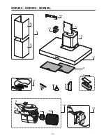
Page 22: ... 22 765 352 251 81 51 4 372 231 271 71 665 221 41 31 21 284 57 211 282 3 XOR24S XOR30S XOR36S ...

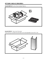
Page 23: ... 23 OPTIONS AND ACCESSORIES Model XORFK01 Ductless Recirculating Filter Kit Model XOEDCR Duct Cover Extension This accessory is available for installation with ceiling heights above 9ft to 10ft ...

Page 24: ...are package packed with the hood and check contents TYPE DESCRIPTION N A 1 8 x 1 2 Screws for attaching the decorative flue to the mounting bracket 2 Duct bracket Aluminum filter 2 piece decorative duct cover dimension shown for reference only 2 1 0 2 7 22 205 34 3027 7 6027 ...

Page 25: ...l chimney extension for ceilings up to 10ft Mounting Height from cooking surface 27 32 Duct Options and Electrical Requirements 6 inch duct required Ductless Option for applications where no ducting in available AC 120v 60Hz 4 35amp Options Optionalductcoverextensionisavailableforceiling heights up to 10ft tall Model XOEDCR Optional recirculating kit if outside venting is available Model XORFK01 X...

Page 26: ...stique en Amérique du Nord Sivousavezbesoind assistancepourvotreproduitXO téléphonez au numéro 800 966 8300 Installation incorrecte Visites à votre domicile pour vous conseiller sur comment utiliser le produit Réinitialisation des interrupteurs Dommages causés après la livraison VOUS DEVEZ VOUS ATTENDRE QUELQUE CHOSE DE PLUS D UN XO En achetant un produit XO vous pouvez être certain d avoir acheté...

Page 27: ...nsporté à l extérieur à travers un conduit d évacuation Ne pas évacuer l air dans des interstices tels qu entre des cloi sons ou des plafonds dans des greniers des espaces confinés ou des garages ATTENTION N utiliser que pour une ventilation générique Cet appareil n est pas propre à l aspiration de matières ou de vapeurs dangereuses ou explosives ATTENTION Afin d éviter des bruits et des dommages ...

Page 28: ...t nécessaire Réchauffer l huile lente ment à faible ou moyenne température F Ne jamais laisser la cuisinière sans surveillance pendant la cuisson G Utiliser systématiquement des ustensiles de cuisine adaptés au type et à la quantité d aliments que l on prépare AVERTISSEMENT AFIN DE RÉDUIRE LES RISQUES DE DOMMAGES AUX PERSONNES EN CAS D INCENDIE PAR INFLAMMATION DES GRAISSES PRESENTES SUR LA CUISIN...

Page 29: ...ng Refrigeration and Air Conditioning Engineers ASHRAE et par les autorités locales préposées C Au cours des opérations de découpage ou de perforation du mur ou du plafond veiller à ne pas endommager les câbles électriques ou d autres canalisations ca chées D L appareil doit toujours être relié à un trou d évacuation vers l extérieur E L unité doit être reliée à la terre AVERTISSEMENT AFIN DE RÉDU...

Page 30: ...it aux exigences pour de bonnes performances en termes de ventilation de toute hotte aspirante Parcours total des conduits RACCORDS DE CANALISATION Cettehottedoitutiliser un conduit rond de 20 cm 8 po raccordan à un tuyau 8 cm x 30 cm 3 1 4 po x 12 po Reportez vous au tableau pour calculer les longueu rs maximales autorisées pour les conduits vers l ex térieur REMARQUE Ne dépassez pasleslongueursm...

Page 31: ...é sur toutes les jonctions INSTALLATION DES TUYAUX NOTE Pour diminuer le risque d incendie utiliser uniquement des tuyaux en métal 1 Décider la position du tuyau entre la hotte et l extérieur 2 Un tuyau court et droit améliore les performances de la hotte 3 De longs tuyaux des coudes et des raccords en diminuent les performances Utiliser ces éléments le moins possible 4 Installer une cheminée au t...

Page 32: ...2027 35 31 809 41 47 22 205 21 2027 4 209 37 Nby 56 2027 Njo Fyusbdups 38 4027 Njo Gjmufsjoh 42 6027 Partie avant de la hotte Partie latérale de la hotte Partie supérieure de la hotte Hauteur de montage et distances DIMENSIONS DU PRODUIT ET DISTANCES XOR24S XOR30S XOR36S ...

Page 33: ...églé le fixer définitive ment à l aide des vis A Fig 2 Pour les différentes installations utiliser les vis et les supports correspondants adaptés au type de mur sur lequel on entend fixer l appareil béton armé placopatre etc Dans le cas où les vis et les supports correspondants fournis avec le produit contrôler qu ils sont bien adaptés au type de mur sur lequel sera fixé la hotte IMPORTANT La hott...

Page 34: ... Ë EFVY öMT BWFD NJTF Ë MB UFSSF t 4J M BMJNFOUBUJPO ÏMFDUSJRVF O FTU QBT DPOGPSNF BVY TQÏDJöDBUJPOT TVTNFOUJPOOÏFT BQ pelez un électricien avant de continuer t 1PTFS MFT DÉCMBHFT EPNFTUJRVFT MF QMVT QSÒT QPTTJCMF EF M JOTUBMMBUJPO BV QMBGPOE PV TVS le mur de support Veuillez consulter les positions des câblages à la page 35 t 3BDDPSEFS MFT DÉCMBHFT EF MB IPUUF BVY DÉCMBHFT EPNFTUJRVFT DPOGPSNÏNFO...

Page 35: ...stème électrique doit être positionnée comme indiqué par l illustration nr 3 Avant d installer l appareil effectuez la fixation de la boîte de l installation électrique v Fig 3 B C D Fig 3B Enlevez les 3 vis déjà serrées Fig 3A Soulevez la boîte de l installation électrique Fig 3C Positionnez la boîte de l installation électrique de sorte qu elle soit en axe avec les trous des vis précedemment enl...

Page 36: ...évissant les 2 vis Fig 4A 2 Cassez le trou du couvercle de la boîte 3 Fixez le conduit d alimentation au couvercle 4 Reliez les fils du hotte à ceux de l alimentation électrique en procédant aux raccordements suivants Fig 4B NOIR L ligne BLANC N neutre VERT JAUNE G terre Un interrupteur bipolaire approprié doit être installé afin de permettre à la hotte de se débrancher du réseau électrique ...

Page 37: ...eil doit être installé à une hau teur minimum de 27 par rapport à une cuisinière électrique et de 32 s il s agit d une cuisinière à gaz ou combinée Si l on utilise un conduit composé de deux éléments la partie supérieure doit alors être reliée à l extérieur de la partie infé rieure Ne pas relier le conduit d aspira tion d air de la hotte à celui utilisé pour aspirer l air chaud ou les fumées prove...

Page 38: ...au moyen des vis A Fig 7 de façon à les aligner avec la hotte et en respectant la distance par rapport au plafond comme indiqué sur la figure 6 Relier la bride C au trou d évacuation d air en utilisant un tube de raccordement Fig 8 Insérer le tube décoratif supérieur à l intérieur du tube inférieur Fixer ce dernier à la hotte au moyen des vis B fournies Fig 8 extraire le tube supérieur en le porta...

Page 39: ... deux cheminées FG en les posant soigneusement sur un plan KIT FILTRE A CHARBON XORFK01 Le kit contient un déviateur d air A 2 vis et 2 che villes expansible B et 2 filtres cassette C Fig 2 Marquer l endroit et faire un trou de fixation à 1 4 pouces du centre de l étrier et introduire la cheville expansible OPTION DE RECIRCULATION SANS TUYAU ...

Page 40: ...me illustré à la figure 3 2 Pour couper le plastique utiliser une lame effilée ou une scie Fig 4 Prendreledéviateurd airAetfairedeuxtrous comme indiqué sur la figure diamètre trou 1 4 pouces Après avoir effectué les deux trous fixer le déviateur d air A à l étrier de fixation des cheminées H Fig 6 Après avoir introduit le déviateur d air sur l étrier et l avoir fixé au mur raccorder le tuyau flexi...

Page 41: ...l étrier et la fixer à l aide des 2 vis E Fig 8 Enlever les panneaux en alumi nium en tirant vers l extérieur le levier 1 et pousser vers le bas 2 Fig 9 Les fi ltres au charbon actif C doi vent s appliquer au groupe d aspiration prévu à l intérieur de la hotte Fig 10 Replacer les panneaux en alumi nium précédemment enlevés Fig 8 ...

Page 42: ...de électroluminescente du bouton F reste alluméesansclignoterjusqu àcequelemoteurreparteen1ère vitesse50minutesplustard Les diodes électroluminescentes F et C recommencent à clignoter pendant 10 minutes et ainsi de suite En appuyant sur n importe quelle touche à l exception des touches de lumière lahotteretourneimmédiatementàsonfonctionnementnormal ex enappuyant sur le bouton D la fonction clean a...

Page 43: ...er l air qui est ensuite renvoyé dans la pièce Les filtres ne sont ni lavables ni régénérables il faut par conséquent les changer au moins tous les quatre mois La saturation du charbon actif dépend de l utilisation plus ou moins prolongée de l appareil du type de cuisine pratiquée et de la régularité du nettoyage du filtre anti graisse t Nettoyez fréquemment la hotte à l intérieur et à l extérieur...

Page 44: ...ourraient adhérer et former par conséquent de la rouille NE PAS laisser des solutions salines des désinfectants de la javelle ou des détergents en contact avec l acier inox pendant une durée excessivement longue Certains de ces produits contiennent des substances chimiques qui pourraient être nuisibles Rincer avec de l eau et essuyer avec un chiffon propre Les surfaces vernies doivent être nettoyé...

Page 45: ...uée que par du personnel spécialisé t 3FNQMBDFNFOU EFT MBNQFT IB logènes Pourremplacerlesampoulesdichroïques débranchez la lampe en la détachant pré cautionneusement du support à l aide d un petit tournevis plat ou d un outil équivalent ATTENTION Pendant cette opération veiller à ne pas griffer la hotte Remplacez les par des ampoules de même type ...

Page 46: ... 46 765 352 251 81 51 4 372 231 271 71 665 221 41 31 21 284 57 211 282 3 XOR24S XOR30S XOR36S ...

Page 47: ...CESSOIRES Kit filtre de recirculation sans tuyaux modèle XORFK01 Modèle XOEDCR Extension de la couverture du tuyau Cet accessoire est disponible pour les installations au plafond avec des hauteurs de plus de 9 10 pieds ...

Page 48: ...lé avec la hotte et vérifiez le contenu TYPE DESCRIPTION N A 1 8 x 1 2 Vis de fixation pour le raccordement du conduit de fumée décorative à l étrier de montage 2 Support de conduit Filtre en aluminium Cache conduit décoratif 2 pièces dimension fournie à titre indicatif uniquement 2 1 0 2 7 22 205 34 3027 7 6027 ...

Page 49: ...teur de montage de la superficie de cuisson 27 32 Tuyaux en option et conditions électriques requises Utiliser des tuyaux de 6 inch Option sans tuyau pour les applications où les tuyaux ne sont pas disponibles AC 120v 60Hz 4 35amp Options L extensiondelacouverturedutuyauestdisponible pour les plafonds d une hauteur jusqu à 10 pieds Modèle XOEDCJ Kit de recirculation en option si la ventilation ver...

Page 50: ... compras realizadas para uso doméstico en América del Norte Si necesita asistencia para su producto XO llame al número 800 966 8300 Instalación incorrecta Visitas a domicilio para recomendaciones sobre el uso del producto Reset de interruptores Daños causados después de la entrega SE ESPERABA MÁS DE UN XO CuandocompraunproductoXOpuedeestarsegurodequeha compradounproductodealtacalidad innovadoryagr...

Page 51: ...n esprays polvo etc ATENCION Para ulterior información y pedidos lea la etiqueta de especificación del producto ADVERTENCIA PARA REDUCIR EL RIESGO DE INCENDIO SACUDIDA ELECTRICA O SDAÑOS A PERSONAS SIGA LAS SIGUIENTES PAUTAS A Use la unidad sólo para finalidades previstas por el fabricante Para eventuales pre guntas contacte el fabricante B Antes de efectuar operaciones de mantención o limpieza a ...

Page 52: ...Use un extinguidor SOLO en caso que 1 Se tenga un extinguidor de Clase ABC y sepa utilizarlo 2 Sea un incendio de dimensiones pequeñas y contenido en el área en la cual ha esta llado 3 Ya hayan sido llamados los bomberos 4 Se puedan afrontar las llamas con la espalda dirigida hacia una salida aBasado en las medidas sobre seguridad antiincendio en la cocina publicadas por el NFPA Una correcta mante...

Page 53: ...VERTENCIA EN CIERTOS CASOS LOS ELECTRODOMESTICOS PUEDEN REVELARSE PELIGROSOS A No controle los filtros mientras la campana se encuentre en función B No toque las luces después de un uso prolungado del aparato C Nunca flamee un alimento bajo la campana D El uso de llamas libres es peligroso para los filtros y puede generar incendios E Controle constantemente los alimentos fritos para evitar que los...

Page 54: ...n con cualquier campana de ventilación Recorrido total de los conductos ACCESORIOS PAR CONDUCTOS Esta campana debe usar un conducto redondo de 8 Puede cambiar a un conducto de 3 1 4 x 12 Utilice esta tabla para cal cular las longitudes máxi mas permitidas para recor ridos de conductos hacia el exterior NOTA No supere las longi tudes equivalentes máxima permitidas Longitud máxima del ducto 100piesp...

Page 55: ...rtificada en todas las juntas INSTALACIÓN DE LA TUBERÍA NOTA Para reducir el riesgo de incendio utilice solo tuberías de metal 1 Decida la posición del tubo entre la campana y el exterior 2 Un tubo corto y recto mejora los rendimientos de la campana 3 Los tubos largos codos y racores reducen los rendimientos Utilice el menor número posible de estos elementos 4 Instale un sombrerete de techo o de p...

Page 56: ...27 35 31 809 41 47 22 205 21 2027 4 209 37 Nby 56 2027 Njo Fyusbdups 38 4027 Njo Gjmufsjoh 42 6027 Parte frontal de la campana Parte lateral de la campana Parte superior de la campana Altura de montaje y distancias DIMENSIONES DEL PRODUCTO Y DISTANCIAS XOR24S XOR30S XOR36S ...

Page 57: ...do el aparato haya sido regulado fíjelo definitivamente usando los tornillos A Fig 2 Para las diferentes instalaciones utilize tornillos y relativos soportes que sean adaptos al tipo de pared en la cual se debe fijar el aparato ej cemento ar mado cartón yeso etc En caso que los tornillos y relativos soportes sean distri buidos junto con el producto controle que sean adaptos para el tipo de pared q...

Page 58: ...O QVFTUB B UJFSSB t 4J MB BMJNFOUBDJØO FMÏDUSJDB OP FTUÈ FO DPOGPSNJEBE DPO MBT JOEJDBDJPOFT EF BSSJCB DPO tacte con un electricista antes de continuar t PMPRVF MPT DBCMFT EPNÏTUJDPT MP NÈT DFSDB QPTJCMF EF MB JOTUBMBDJØO FO FM UFDIP P FO la pared de soporte Consulte las posiciones de los cables en la página 59 t POFDUF MPT DBCMFT EF MB DBNQBOB B MPT DBCMFT EPNÏTUJDPT FO DPOGPSNJEBE DPO MPT DØ dig...

Page 59: ...ainstalacióndel aparato efectuar la fijación de la caja planta eléctrica tal como indicado en la Fig 3 B C D Fig 3B Quitar los 3 tornillos fijados Fig 3A Levantar la caja planta eléctrica Fig 3C Colocar la caja planta eléctrica de modo que esté alineada con los agujeros de los tornillos que fueron quitados precedentemente y reatornillar ...

Page 60: ... 4A 2 Realice el orifico de la tapa de la caja 3 Fije el conducto de alimentación a la tapa 4 Conecte los cables de la campana con los de la alimentación eléctrica realizando las siguientes conexiones Fig 4B NEGRO L línea BLANCO N neutro VERDE AMARILLO G tierra Se debe instalar un interruptor bipolar de una medida apropiada que permita que la campana se conecte a la alimentación eléctrica B C Fig ...

Page 61: ...tados El electrodoméstico debe ser instalado a una altura mínima de 27 sobre los hor nos eléctricos y de 32 en caso se usen hornos a gas o combinados Si se utiliza una tubería compuesta de 2 partes la parte superior debe ser colocada al ex terno de la inferior No conecte la tubería de aspiración del aire de la campana a aquel usado para aspirar el aire calien te o humo de otros electrodomésticos q...

Page 62: ...on los tornillos A Fig 7 de modo que se alínee con la campana y respetando la distancia con el techo indicada en la Fig 6 Conecte el reborde C al agujero de evacuación del aire utilizando un tubo de enlace Fig 8 Introduzca el tubo decorativo superior dentro del tubo inferior Fije este último a la campana mediante los tornillos B proporcionados Fig 8 extraiga el tubo superior llevándolo hasta la ab...

Page 63: ...as dos chimeneas F G apoyándolas cuidadosamente en una superficie FILTRO DE CARBÓN ACTIVO XORFK01 El kit contiene un desviador de aire A 2 torni llos y 2 tacos de expansión B y 2 filtros de cajón C Fig 2 Marcar y efectuar un agujero de fijación a 1 4 pulgadas del centro de la brida e introducir el taco de expansión OPCIÓN DE RECIRCULACIÓN SIN TUBO ...

Page 64: ...ujeros como mostrado en la ilustración diáme tro del agujero 1 4 pulgadas Una vez efectua dos los dos agujeros fijar el desviador de aire A a la brida de fijación de chimeneas H Fig 5 Fijar definitivamente el desviador de aire a la pared con un tornillo de fijación agujero anteriormente efectuado en la Fig 2 Fig 6 Una vez introducido el desviador de aire en la brida y fijado a la pared conectar el...

Page 65: ...sta la brida y fijarla con los 2 tornillos E Fig 8 Quitar los paneles de aluminio ti rando hacia fuera la palanca 1 y empujar hacia abajo 2 Fig 9 Los fi ltros al carbón activo C se de ben aplicar al grupo aspirador situado en el interior de la campana Fig 10 Volver a colocar los paneles de aluminio anteriormente quitados Fig 8 ...

Page 66: ...tempora neamente Terminado este período el motor se apaga y el led del botón F se mantiene encendido con una luz fija por 50 minutos En ese momento el motor reparte en la primera velocidad los leds F y C recomienzan a relampagear por 10 minutos y se repite el ciclo Presionando cualquier botón a excepción de las luces la campana inmediatamente regresa a su funcionamiento normal ej presionando el bo...

Page 67: ...placement et de lavage peut entraîner un risque d incendie des filtres anti graisse t FT öMUSFT Ë DIBSCPO BDUJG servent à filtrer l air qui est ensuite renvoyé dans la pièce Les filtres ne sont ni lavables ni régénérables il faut par conséquent les changer au moins tous les quatre mois La saturation du charbon actif dépend de l utilisation plus ou moins prolongée de l appareil du type de cuisine p...

Page 68: ... NO deje las incrustaciones durante demasiado tiempo en la campana NO utilice estropajos o cepillos de acero Sobre la superficie podrían adherirse partículas de acero con la consiguiente formación de herrumbre NO deje soluciones salinas desinfectantes lejía o detergentes en contacto con el acero inoxidableduranteuntiempoexcesivamentelargo Algunosdeestosproductoscontienen sustancias químicas que po...

Page 69: ... personal es pecializado t 4VTUJUVDJØO EF MBT MÈNQBSBT IBMØHFOBT Para sustituir las lámparas dicroicas desconecte la lámpara aflojándola cuidadosamente del portalámpara con la ayuda de un pequeño destornillador plano o una herramienta equivalente ATENCIÓN Al efectuar esta operación tenga cuidado de no arañar la campana Sustitúyalas por lámparas del mismo tipo ...

Page 70: ... 70 765 352 251 81 51 4 372 231 271 71 665 221 41 31 21 284 57 211 282 3 XOR24S XOR30S XOR36S ...

Page 71: ...ES Y ACCESORIOS Kit filtro de recirculación sin tubería modelo XORFK01 Modelo XOEDCR Extensión de la cubierta del tubo Este accesorio está disponible para instalaciones de techo con alturas superiores a 9ft 10ft ...

Page 72: ...e montaje 2 Support de conduit Filtro de aluminio Cache conduit décoratif 2 pièces dimension fournie à titre indicatif uniquement 2 1 0 2 7 22 205 34 3027 7 6027 PREPARACIÓN PARA LA INSTALACIÓN Controle los elementos para la instalación Ubique el paquete de hardware embalado con la campana y verifique los contenidos ...

Page 73: ......

Page 74: ......

Page 75: ......

Page 76: ...a de montaje de la superficie de cocción 27 32 Duct Options and Electrical Requirements Se deben usar tubos de 6 inch Opción sin tubo para aplicaciones en las que no están disponibles los tubos AC 120v 60Hz 4 35amp Opciones La extensión de la cubierta del tubo está disponible para techos con altura de hasta 10 ft Modelo XOEDCR Kit de recirculación opcional disponible si la ventilación hacia el ext...

Reviews: