- 13 -
B
X
A
B
B
27” to 32”
installation
1
2
3
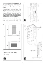
- Remove the structure from the packaging and
remove the 2 screws
A
to separatethe upper
part from the lower part
(Fig.1)
.
- Position hole template on the ceiling paying
attention that the arrow is positioned on the
same side as the appliance controls
(Fig.2)
.
Make 4, Ø8 holes in the ceiling and drive in 3
screws without completely tightening them. Pay
attention not to insert the screw into the hole
marked with an
X
on the hole template (the
screws and expansion plugs must be suitable
for the type of wall).
- Take the upper part of the structure
B (Fig.3)
and insert the 3 slots onto the 3 screws that are
not completely tightened. Rotate slightly to fit
(Fig.3)
. Drive in the fourth screw
X
and tighten
the remaining 3 to allow definitive blocking of
the upper part ofstructure
B
.
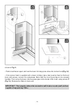
- Take the lower part of the telescopic structure
C
and insert it into the upper structure
B (Fig.4)
.
Adjust the height by referring to the amounts in-
dicated in
(Fig.5)
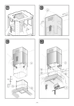
and block it usingthe 8 screws
G
that are supplied
(Fig.6)
.
- Fix the flexible pipe to the prepared air eva
-
cuation hole
(Fig.7)
.
- Take the upper chimney piece and fix it to the
Summary of Contents for XOMI ISLAND XOMI36GC
Page 1: ...I worked really hard on this manual so please read it XOMI ISLAND MODELS XOMI36GC XOMI42GC ...
Page 2: ......
Page 15: ... 15 7 8 9 A L N O N O L Max 3 mm O O 10 ...
Page 37: ... 37 7 8 9 A L N O N O L Max 3 mm O O 10 ...
Page 46: ...He trabajado mucho en este manual así que léalo XOMI ISLAND MODELOS XOMI36GC XOMI42GC ...
Page 59: ... 59 7 8 9 A L N O N O L Max 3 mm O O 10 ...
Page 68: ...3011000130700 00 ...


