background image

XNET User Manual


61 /

 71 

2

2

.

.

5

5

.

.


W

W

D

D

R

R

/

/

B

B

L

L

C

C

/

/

E

E

C

C

L

L

P

P

S

S


Select “WDR/BLC/ECLPS” using the UP or DOWN button. You can select between “OFF”, “WDR”, “BLC” and 
“ECLPS” using the LEFT or RIGHT button. Select the desired menu and then press the MENU button. 
 

2

2

.

.

5

5

.

.

1

1

.

.


W

W

D

D

R

R


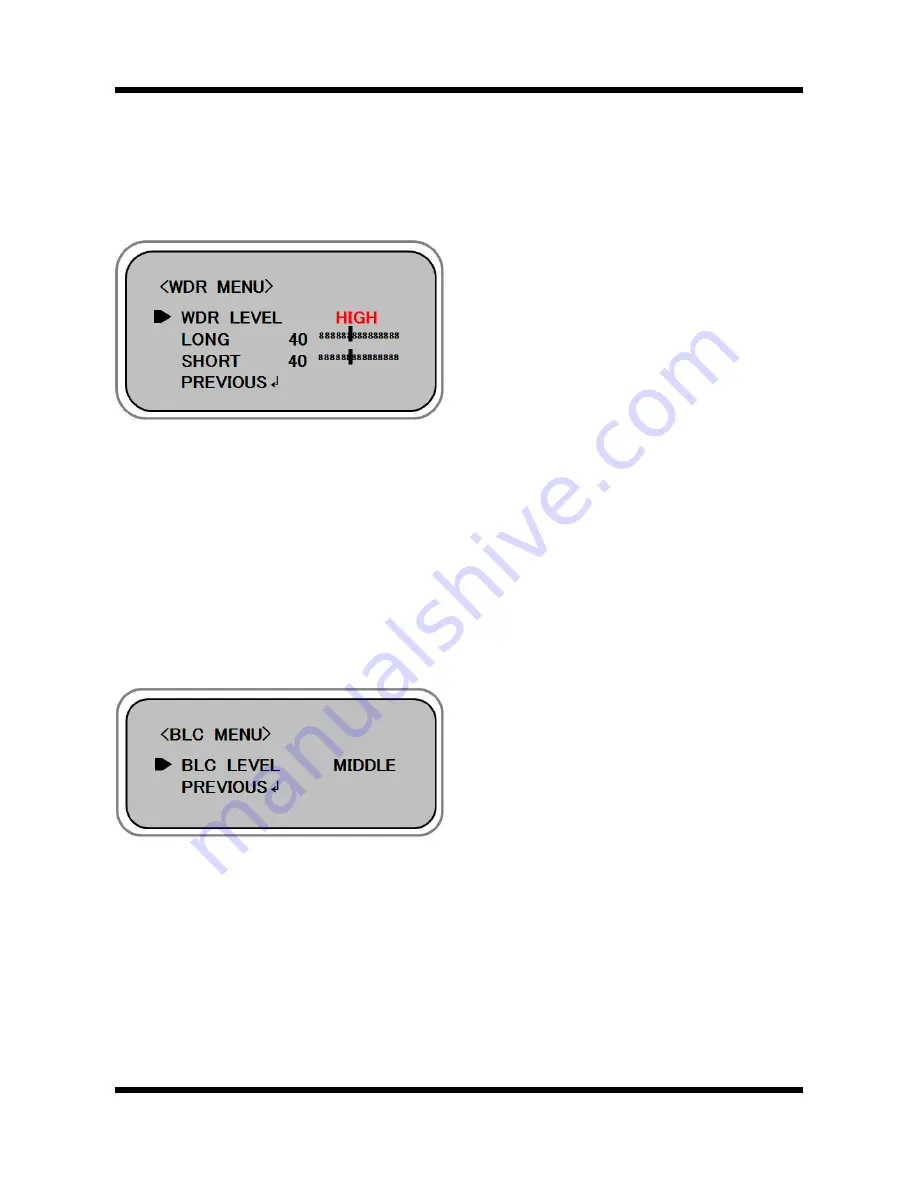
1) WDR LEVEL 

You can select between “LOW”, “MIDDLE” and “HIGH” using the LEFT or RIGHT button. 
 

2) LONG 

You can select between 0 ~ 60 using the LEFT or RIGHT button. 
 

3) SHORT 

You can select between 0 ~ 60 using the LEFT or RIGHT button. 
 

2

2

.

.

5

5

.

.

2

2

.

.


B

B

L

L

C

C


BLC LEVEL 

You can select between “LOW”, “MIDDLE” and “HIGH” using the LEFT or RIGHT button. 


Summary of Contents for IGB1110NF

Page 1: ...Ver 1 0 XNET IGB1110PF IGB1110NF User Manual...

Page 2: ...re or the manufacturer before disassembling the product for alteration or repair XNET is a trademark of CNB Technology Inc z This product complies for CE Europe and FCC USA regulations for industrial...

Page 3: ...nfiguring Video 27 1 13 Configuring RTP RTSP 29 1 14 Configuring Camera Condition 31 1 15 Configuring the Network TCP IP parameters 33 1 18 Configuring IP Filtering 35 1 19 Configuring HTTP 37 1 20 Co...

Page 4: ...0 2 5 WDR BLC ECLPS 61 2 5 1 WDR 61 2 5 2 BLC 61 2 5 3 ECLIPSE 62 2 6 WHITE BAL 63 2 6 1 ATW1 63 2 6 2 ATW2 63 2 6 3 PUSH 63 2 6 4 MANUAL 63 2 7 3D DNR 64 2 7 1 LEVEL 64 2 7 2 GLOBAL MOTION 64 2 8 IMA...

Page 5: ...XNET User Manual 5 71 2 9 8 FACTORY RESET 70 2 9 9 COMM SET 71 2 10 SAVE EXIT 71...

Page 6: ...x xp pl lo or re er r Type the IP Address of the XNET product in the address bar and press enter e g http 192 168 123 100 If the HTTP port has been changed from the default value enter the new port as...

Page 7: ...is the only way to regain access However since this will retrieve all default settings you need to configure the network settings using IP installer software again For security purpose it is recommen...

Page 8: ...g C Ca am me er ra a When you log in as an administrator XNET s Basic Setup page will appear as shown in Figure 1 2 Setup pages for different features can be accessed from this page Access to each fe...

Page 9: ...on Access Administrator Operator Viewer Index Page Multi Index Page PTZ Page Motion Page Users Setup Page Date Time Setup Page Multi Viewer Setup Page Maintain Server Setup Page System Log Setup Page...

Page 10: ...er r I In nd de ex x h ht tm ml l When you access an XNET product Web Viewer page will appear automatically Viewer area displays the video output from the camera and menu bar contains taps that lead t...

Page 11: ...er to 1 27 for detail Live View Opens up Index View page Index View Page will display Video as well as setting up Stream Protocol TCP UDP and Codec when using Dual Stream Multi View Opens up Multi Vie...

Page 12: ...71 1 1 4 4 S St ta at tu us s W Wi in nd do ow w Status page displays XNET System s Version and its Ethernet address Click Status button to open the page shown in Figure 1 4 Figure 1 4 Status Page In...

Page 13: ...on nf fi ig gu ur ri in ng g U Us se er rs s This can give or limit authority to users for controlling Video and other features of XNET system Click Users button to open the page shown in Figure 1 5...

Page 14: ...h user Select a user in User Listbox enter new Password User Group and click modify button to save the changes Updated detail can be viewed in User List Box Remove Removes a user Select a user in User...

Page 15: ...ser Manual 15 71 1 1 6 6 S Se et tt ti in ng g D Da at te e T Ti im me e This page will change Date and Time of XNET system Click Date Time to open the page shown in Figure 1 6 Figure 1 6 Date and Tim...

Page 16: ...ime Time Mode Sets Date and Time of the Server Default None Synchronize with computer time Synchronizes time and date of Client PC to Server Synchronize with NTP server Synchronizes server s time and...

Page 17: ...ri in ng g M Mu ul lt ti i V Vi ie ew we er r Up to 3 cameras connected to XNET s network can be displayed as sub cameras simultaneously in Multi View page Click Multi Viewer to open the page shown in...

Page 18: ...entered This can only be enabled when IP Address User Name and Password is properly entered Default Disable Default Disable 2nd IP Address Enter 2nd Channel s IP Address 2nd User name Enter 2nd Chann...

Page 19: ...r Manual 19 71 1 1 8 8 C Co on nf fi ig gu ur ri in ng g P PT TZ Z This configures XNET s PTZ server information Click PTZ Configuration to open the page shown in Figure 1 8 Figure 1 8 PTZ Configurati...

Page 20: ...ile from PTZ Protocol List and click Set button to activate the protocol Del Deletes PTZ Protocol File Select Protocol File from PTZ Protocol List and click Del button to delete the selected protocol...

Page 21: ...fi ig gu ur ra at ti io on ns s This page configures system parameters such as system restart factory default settings system upgrade saving configurations saving images and other additional features...

Page 22: ...the XNET while the upgrade is in process It might cause a system error Upgrade File can be downloaded from http www cnbtec com BackUp Backup This saves current configurations in Client PC Back up file...

Page 23: ...0 0 G Ge en ne er ra at ti in ng g L Lo og g R Re ep po or rt t Log report contains detailed information about XNET s image setup and error Click Log Report button to open the page shown in Figure 1 1...

Page 24: ...ed in the xNet product Log Message file can be sorted with date and index Click Load List button to view message list in the Listbox Logs View Select a file from the Log List and click Logs view butto...

Page 25: ...l 25 71 1 1 1 11 1 C Co on nf fi ig gu ur ri in ng g A Au ud di io o Xnet s Audio features can be configured in this page Click Audio button to open the page shown in Figure 1 11 Figure 1 11 Audio con...

Page 26: ...lt Microphone Microphone input can be used when users send their voice over XNET system Line input takes the input from an audio device to send over XNET Audio sent to XNET can be played at a Client s...

Page 27: ...l 27 71 1 1 1 12 2 C Co on nf fi ig gu ur ri in ng g V Vi id de eo o XNET s Video features can be configured in this page Click Video button to open the page shown in Figure 1 12 Figure 1 12 Video Con...

Page 28: ...CP Callback Control If this checkbox is selected the value of the Frame rate above is automatically adjusted in case overload occurs by sharing lack bandwidth with bit transmission the Rate bit value...

Page 29: ...Manual 29 71 1 1 1 13 3 C Co on nf fi ig gu ur ri in ng g R RT TP P R RT TS SP P This is related to XNET s DDNS server information Click RTP RTSP to open the page shown in Figure 1 13 Figure 1 13 RTP...

Page 30: ...34 The default is 2000 RTP End Port Enter RTP End Port between 1124 and 65535 The default is 3000 Maximum number of users to connect Enter the maximum allowable number of users connected to the Stream...

Page 31: ...ng g C Ca am me er ra a C Co on nd di it ti io on n This page confgures XNET s camera features Click Camera Condition button to open the page shown in Figure 1 14 Figure 1 14 Camera Conditions Page F...

Page 32: ...Displays the OSD menu or Executes the item in the case that the OSD menu is being displayed Menu Off Ends the use of the OSD menu Direction Key Moves the view in the x and y direction Back Moves to t...

Page 33: ...f fi ig gu ur ri in ng g t th he e N Ne et tw wo or rk k T TC CP P I IP P p pa ar ra am me et te er rs s This configures XNET s network related parameters Click TCP IP button to open the page shown in...

Page 34: ...mask Enter Subnet mask Use this when you want to access only from the same subnet by masking out upper portion of the IP address Use 255 255 255 255 when you want to connect from one PC only Default...

Page 35: ...71 1 1 1 18 8 C Co on nf fi ig gu ur ri in ng g I IP P F Fi il lt te er ri in ng g This configures IP Filters for XNET product Click IP Filtering button to open the page shown in Figure 1 18 Figure 1...

Page 36: ...s Listbox Up to 20 IP addresses can be added Remove Removes an IP address from IP Filtering listbox Select the IP address to remove and click Remove button to remove it from the list The updated list...

Page 37: ...User Manual 37 71 1 1 1 19 9 C Co on nf fi ig gu ur ri in ng g H HT TT TP P This configures HTTP port to access XNET s webpage Click HTTP button to open the page shown in Figure 1 19 Figure 1 19 HTTP...

Page 38: ...t to access the webpage Default port is 80 and any other port number has to be entered at the end of the ip address when accessing e g When using HTTP Port 8080 enter http 192 168 123 100 8080 Save Ap...

Page 39: ...n nD DN NS S B Bo on nj jo ou ur r UPnP is a protocol for IP installer software You can enable or disable this UPnP and you can also use a Friendly Name DynDNS configures XNET s DDNS server informatio...

Page 40: ...Enable Anonymous Enables or disables DynDNS Anonymous feature When enabled DDNS service is used without going through authentication at Autoipset com DDNS server Alias Host Name Enter a Host Name for...

Page 41: ...XNET s CMS Server information Click CMS to open the page shown in Figure 1 21 Figure 1 21 CMS Page ITEM DESCRIPTION CMS CMS port Enter CMS port number for communication with CMS between 1 and 65535 Th...

Page 42: ...al 42 71 1 1 2 22 2 C Co on nf fi ig gu ur ri in ng g E Ev ve en nt t T Ty yp pe e This is related to XNET s DDNS Server information Click Event Types to view page shown in Figure 1 22 Figure 1 22 Eve...

Page 43: ...tivated the unit will monitor event Alarm all the time During Time is selected while Event Alarm is activated the unit will monitor event Alarm during the time period specified Event Schedules Setting...

Page 44: ...71 1 1 2 23 3 C Co on nf fi ig gu ur ri in ng g S Se en ns so or r A Al la ar rm m This is related to XNET s DDNS server information Click Sensor Alarm to open the page shown in Figure 1 23 Figure 1 2...

Page 45: ...elects the signal type for Alarm Input Port between Normally Close and Normally Open Alarm Setting Out Interval Configures interval between repeating Alarm Out signals between 1 and 3 seconds Save App...

Page 46: ...l 46 71 1 1 2 24 4 S SM MT TP P S Se et tu up p This configures mailing out method of Alarm Images once event occurred in the XNET system Click SMTP button to open the page shown in Figure 1 24 Figure...

Page 47: ...r password mail address etc needs to be configured Enable SMTP Authorization Enables or disables the use of SMTP authorization when using external mail server SMTP Server Name Enter the name of extern...

Page 48: ...2 25 5 C Co on nf fi ig gu ur ri in ng g F FT TP P This configures how the Alarm Images get sent out using FTP once event occurred in the XNET system Click FTP button to open the page shown in Figure...

Page 49: ...to receive the Alarm Images FTP Port Enter the port number for the FTP server to send Alarm Images to in the event processing Login Information User Name Enter the user name of the FTP server to send...

Page 50: ...controls XNET IGP1030 s Digital PTZ Click PTZ button in Operator mode to open the page shown in Figure 1 26 Figure 1 26 Digital PTZ page ITEM DESCRIPTION Digital PTZ Action Bar Direction Key This move...

Page 51: ...Co on nf fi ig gu ur ri in ng g a an nd d o op pe er ra at ti in ng g P PT TZ Z This controls XNET s IGP1030 INS2000 and IJB2000 PTZ movement Click PTZ button in Operator mode to open the page shown...

Page 52: ...oves the view in the x and y direction Wide Zooms Out Tele Zooms In Far Focuses Out Near Focuses in Push AF Automatically adjust the focus Set Preset Saves the current position to the values in the Pr...

Page 53: ...Mo ot ti io on n D De et te ec ct ti io on n a ar re ea a This defines areas that detect motion and up to three different areas can be defined in each channel Click Motion button in Operator mode to...

Page 54: ...tivity Sets sensitivity for detecting motions 1 being the least sensitive and 10 being the most sensitive The user needs to configure this according to their applications and circumstances Defining Mo...

Page 55: ...gures viewing of up to 4 different camera images simultaneously Click button in Administrator mode to open the page shown in Figure 1 29 The video from the XNET product gets displayed on top left and...

Page 56: ...the MENU button Use the four direction buttons to move to a desired letter and select the letter by pressing the MENU button Repeat this to enter multiple letters You can enter up to 15 letters z Move...

Page 57: ...e DC VIDEO control signal Select DC VIDEO using the LEFT or RIGHT button DC IRIS RESET The optimized DC level for each lens can be different from the camera s default DC level The proper level may be...

Page 58: ...ou can adjust between 0 100 using the LEFT or RIGHT button 2 2 3 3 3 3 S SH HU UT TT TE ER R Select SHUTTER using the UP or DOWN button You can select AUTO OFF A FLK or adjust the shutter speed betwee...

Page 59: ...LE and HIGH using the LEFT or RIGHT button z DAY NIGHT mode is changed by source of light from bright to dark by HIGH MID LOW order 2 FILTER DLY Select FILTER DLY using the UP or DOWN button You can s...

Page 60: ...LOW MIDDLE and HIGH using the LEFT or RIGHT button z DAY NIGHT mode is changed by source of light from bright to dark by HIGH MID LOW order 2 FILTER DLY Select FILTER DLY using the UP or DOWN button Y...

Page 61: ...t the desired menu and then press the MENU button 2 2 5 5 1 1 W WD DR R 1 WDR LEVEL You can select between LOW MIDDLE and HIGH using the LEFT or RIGHT button 2 LONG You can select between 0 60 using t...

Page 62: ...sired area and then select one of the ON OFF by pressing the UP or DOWN button To exit out from the divided screen by pressing the MENU button 2 ALL AREA SET To set all areas select ALL AREA SET using...

Page 63: ...adjusted on the special picture of the current camera screen z Select PUSH using the LEFT or RIGHT button and then press the MENU button 2 2 6 6 4 4 M MA AN NU UA AL L To access WB MANUAL menu select...

Page 64: ...utton and then press the MENU button 2 2 7 7 1 1 L LE EV VE EL L Select LEVEL using the UP or DOWN button You can adjust between 0 63 using the LEFT or RIGHT button 2 2 7 7 2 2 G GL LO OB BA AL L M MO...

Page 65: ...then press the MENU button to access DIGITAL ZOOM menu 1 ZOOM Select ZOOM using the UP or DOWN button You can control a digital zoom of X1 00 X6 13 using the LEFT or RIGHT button 2 DZOOM PAN Select D...

Page 66: ...LEFT or RIGHT button 2 2 8 8 4 4 C CO ON NT TR RA AS ST T Select CONTRAST using the UP or DOWN button You can adjust between 0 100 using the LEFT or RIGHT button 2 2 8 8 5 5 S SH HA AR RP PN NE ES SS...

Page 67: ...ect CAMERA ID using the UP or DOWN button Select ON using the LEFT or RIGHT button and then press the MENU button to access the SET CAMERA ID menu 1 CAMERA ID Select CAMERA ID between 000 255 using th...

Page 68: ...u can enlarge or decrease the horizontal size of the selected ZONE area by using the LEFT or RIGHT button 16 100 4 HEIGHT Select HEIGHT using the UP or DOWN button You can enlarge or decrease the vert...

Page 69: ...OLOR using the UP or DOWN button You can select between GRAY WHITE RED GREEN BLUE YELLOW BLACK using the LEFT or RIGHT button 4 WIDTH Select WIDTH using the UP or DOWN button You can enlarge or decrea...

Page 70: ...T mode 2 L L Line Lock mode z L L mode When using AC power at 60Hz frequency you can use the L L type synchronization z L L PHASE mode When using AC power at 60Hz frequency you can use the L L type sy...

Page 71: ...9600 19200 38400 and 57600 using the LEFT or RIGHT button 2 SAVE REBOOT To apply the changed BAUD RATE select SAVE REBOOT using the UP or DOWN button and then press the MENU button 2 2 1 10 0 S SA AV...

Reviews: