background image


XD-9010-TS3-W-EN Rev A  04/2009 

Installation & Operation Manual  


16 


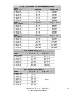
QUIET FIRE BURNER - GAS REQUIREMENTS (INLET) 

Oven 
Single Stack 

Natural Gas 

Propane Gas 

1832-TS3-W 

15.23 kw 

15.23 kw 

2440-TS3-W 

19.03 kw 

19.03 kw 

3240-TS3-W 

26.35 kw 

26.35 kw 

3255-TS3-W 

43.92 kw 

43.92 kw 

3855-TS3-W 

43.92 kw 

43.92 kw 

3270-TS3-W 

46.85 kw 

46.85 kw 

3870-TS3-W 

46.85 kw 

46.85 kw 

Oven 
Double Stack 

Natural Gas 

Propane Gas 

1832-TS3-W 

30.46 kw 

30.46 kw 

2440-TS3-W 

38.06 kw 

38.06 kw 

3240-TS3-W 

52.70 kw 

52.70 kw 

3255-TS3-W 

87.84 kw 

87.84 kw 

3855-TS3-W 

87.84 kw 

87.84 kw 

3270-TS3-W 

93.70 kw 

93.70 kw 

3870-TS3-W 

93.70 kw 

93.70 kw 

Oven 
Triple Stack 

Natural Gas 

Propane Gas 

1832-TS3-W 

45.69 kw 

45.69 kw 

2440-TS3-W 

57.09 kw 

57.09 kw 

3240-TS3-W 

79.05 kw 

79.05 kw 

3255-TS3-W 

131.76 kw 

131.76 kw 

3855-TS3-W 

131.76 kw 

131.76 kw 

3270-TS3-W 

140.55 kw 

140.55 kw 

3870-TS3-W 

140.55 kw 

140.55 kw 


GAS ORIFICE SIZES (per oven) 

Oven 

Natural Gas 

Main Orifice ID 

Manifold Pressure 

1832-TS3-W 

3.33 mm 

8.75 mbar 

2440-TS3-W 

3.71 mm 

8.75 mbar


3240-TS3-W 

4.32 mm 

8.75 mbar


3255-TS3-W 

5.56 mm 

8.75 mbar


3855-TS3-W 

5.56 mm 

8.75 mbar


3270-TS3-W 

4.09 mm 

11.20 mbar


3870-TS3-W 

4.09 mm 

11.20 mbar


GAS ORIFICE SIZES (per oven) 

Oven 

Propane Gas 

Main Orifice ID 

Manifold Pressure 

1832-TS3-W 

2.08 mm 

2440-TS3-W 

2.29 mm 

3240-TS3-W 

2.62 mm 

3255-TS3-W 

3.28 mm 

3855-TS3-W 

3.28 mm 

3270-TS3-W 

2.52 mm 

3870-TS3-W 

2.52 mm 

25 mbar 

Summary of Contents for 1832-TS3-W

Page 1: ...trations of substances harmful to health in the room in which it is installed This appliance needs an unobstructed flow of fresh air for satisfactory combustion and must be installed in a suitably ventilated room in accordance with current regulations This appliance should be serviced by qualified personnel at least every 12 months or sooner if heavy use is expected XD 9010 TS3 W EN Rev A 04 2009 ...

Page 2: ...he installed position Keep the area free and clear of combustible material DO NOT SPRAY AEROSOLS IN THE VICINITY OF THIS APPLIANCE WHILE IT IS IN OPERATION Ovens are certified for installation on combustible floors An electrical schematic is located inside the control box of the oven and on pages 32 34 of this manual Disconnect input power to the unit before performing any maintenance This unit re...

Page 3: ... and facilities including state of the art CAD CAM designing and fabricating software and machine tools The company has also developed ways to build quality into its products at each stage of the manufacturing process both through extensive use of automation and most importantly through an awareness that people are the central element in quality control Wolfe Electric Inc wants you to be totally s...

Page 4: ...RCHASER S RESPONSIBILITY 19 5 3 ASSEMBLY INSTRUCTIONS 19 5 4 PHYSICAL LOCATION SPACING REQUIREMENTS 20 5 5 ELECTRICAL SUPPLY 20 5 6 GAS SUPPLY 20 5 7 CASTERS 21 5 8 RESTRAINT 21 5 9 VENTILATION 21 5 9 1 VENTILATION REQUIREMENTS 21 5 9 2 VENTILATION GUIDELINES 22 5 9 3 VENTILATION PERFORMANCE TEST 22 5 9 4 HOOD INTERCONNECTION 23 5 9 5 FIRE SUPPRESSION 23 5 9 6 MAINTENANCE 25 5 10 CLEANING 25 6 TRO...

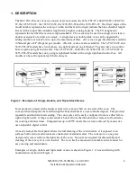
Page 5: ...only a single right hand burner with a single right hand control box All models can have the optional split belt conveyor Figure 1 Examples of Single Double and Triple Stack Ovens Food product is placed on the stainless steel wire conveyor belt on one side of the oven The conveyor then transports the food through the bake chamber at a user controlled speed This provides repeatable and uniform food...

Page 6: ...XD 9010 TS3 W EN Rev A 04 2009 Installation Operation Manual 5 Figure 2 TS3 W Front View Figure 3 Right Hand Control Box All TS3 W Models Figure 4 Left Hand Control Box 3270 TS3 W and 3870 TS3 W ...

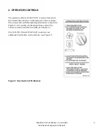
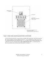
Page 7: ...Control Box which is on the right side of the oven also The oven switch with the operating instructions is shown in Figure 5 Also nearby are the temperature control the conveyor control and the fuse bank see Figure 6 The 3270 TS3 W and 3870 TS3 W ovens have an additional Control Box on the left side see Figure 7 Figure 5 Oven Switch TS3 Models ...

Page 8: ...umber It is very important to use only the fuses listed Using larger or smaller fuses than what is labeled on the oven can cause serious damage to the operator and or the oven and will also void any and all warranties See Figure 6 A conveyor control is located at the top of the panel and a temperature control is located mid panel A Flow Path Pressure Generating fan with washable filter is near the...

Page 9: ...ol Panel This panel houses the fuses for the equipment inside the left hand control box A second temperature control is also used for controlling the burner on the left half of the oven This allows for two different temperature zones within these ovens for cooking flexibility with a maximum delta of 10º C Another Flow Path Pressure Generating fan is near the bottom of the panel See Figure 7 ...

Page 10: ... Panel Split Belt Conveyor TS3 W A popular option on the XLT oven is the split conveyor belt This allows for 2 different conveyor speeds through the oven Figure 8 shows the right hand control panel when the split belt option is present The difference is that a second conveyor control is also present ...

Page 11: ...eyor if not already running see Figure 6 6 Adjust the conveyor controller to desired belt time see Figure 6 7 Allow about 30 minutes for the oven to reach desired operating temperature This oven is not capable of being safely placed in operation in the event of a power failure No attempt should be made to operate this oven during power failure 3 1 2 FOR THE 3270 TS3 W AND 3870 TS3 W MODELS 1 Turn ...

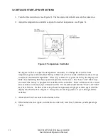
Page 12: ...he desired temperature After Up or Down key press inactivity the display will blink once indicating that the set point temperature has been set The Func and Man keys are used at the factory to program the variables in the controller These variables can be viewed but are locked in memory by an internal switch It is recommended that the Func and Man keys be left alone If either of these keys have be...

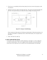
Page 13: ...e 10 Conveyor Control Display These controls are factory preset at 4 00 minutes minimum and 14 00 minutes maximum If a belt time is desired that is outside these limits contact Wolfe Electric Inc for proper service procedures 7 Allow 30 minutes for warm up 3 3 SHUT DOWN INSTRUCTIONS To turn the oven off just turn Oven switch to off position See Figure 5 Do not unplug the oven from electrical power...

Page 14: ...XD 9010 TS3 W EN Rev A 04 2009 Installation Operation Manual 13 4 SPECIFICATIONS Figure 11 Oven Size Specification Drawing ...

Page 15: ...XD 9010 TS3 W EN Rev A 04 2009 Installation Operation Manual 14 ...

Page 16: ...220 230 240 VAC 5 8 6 1 6 4 Single 50 Hz Double Stack Volts Amps Phase Frequency 1832 TS3 W 6 0 6 4 6 8 2440 TS3 W 6 0 6 4 6 8 3240 TS3 W 6 0 6 4 6 8 3255 TS3 W 6 0 6 4 6 8 3855 TS3 W 6 0 6 4 6 8 3270 TS3 W 11 6 12 2 12 8 3870 TS3 W 220 230 240 VAC 11 6 12 2 12 8 Single 50 Hz Triple Stack Volts Amps Phase Frequency 1832 TS3 W 9 0 9 6 10 2 2440 TS3 W 9 0 9 6 10 2 3240 TS3 W 9 0 9 6 10 2 3255 TS3 W ...

Page 17: ... W 93 70 kw 93 70 kw Oven Triple Stack Natural Gas Propane Gas 1832 TS3 W 45 69 kw 45 69 kw 2440 TS3 W 57 09 kw 57 09 kw 3240 TS3 W 79 05 kw 79 05 kw 3255 TS3 W 131 76 kw 131 76 kw 3855 TS3 W 131 76 kw 131 76 kw 3270 TS3 W 140 55 kw 140 55 kw 3870 TS3 W 140 55 kw 140 55 kw GAS ORIFICE SIZES per oven Oven Natural Gas Main Orifice ID Manifold Pressure 1832 TS3 W 3 33 mm 8 75 mbar 2440 TS3 W 3 71 mm ...

Page 18: ...870 Number of injectors 1 per burner Main burner aeration opening size Fixed Ignition Electric Direct Spark Igniter Inlet connection BSP 3 4 male thread NOTE For proper operation measure the gas pressure see Figure 12 with all gas appliances such as furnace hot water heater oven s etc a off and b with all gas appliances on Figure 12 Gas Pressure Check Quiet Fire Burner Contact Wolfe Electric Inc a...

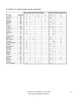
Page 19: ...DE X X X Austria AT X X Belgium BE X X Denmark DK X X Spain ES X X X Finland FI X X France FR X X X X Greece GR Ireland IE X X X Iceland IS Italy IT X X Luxembourg LU Norway NO X Netherlands NL X X X Portugal PT X X X United Kingdom GB X X X Sweden SE X X Switzerland CH X X X X Slovenia SI X Slovakia SK X Cyprus CY X X X Estonia EE X Latvia LT X Lithuania LV Malta MT X X Hungary HU X X Poland PL X...

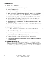
Page 20: ...device and make sure that it guards against transmission of strain to the gas line and electric cord 7 Test the exhaust hood using a smoke candle to determine the amount of combustion products removed 5 2 PURCHASER S RESPONSIBILITY Note All installations must conform to local building and mechanical codes It is the responsibility of the purchaser 1 To see that the gas and electric utilities are in...

Page 21: ...s page 29 5 5 ELECTRICAL SUPPLY All XLT ovens require a 220 240VAC power supply See General Specifications Chart for the electrical power requirements When installed the appliance must be electrically grounded in accordance with local codes 5 6 GAS SUPPLY The gas supply should have a gas meter and regulator large enough to handle all of the gas appliances such as the furnace hot water heater and o...

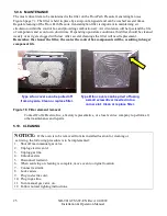
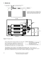
Page 22: ...n of performing any service functions that require removal of the restraint insure that it is correctly re attached to the oven see Figure 13 One restraint is required per oven stack Figure 13 Restraint view 5 9 VENTILATION 5 9 1 VENTILATION REQUIREMENTS Most gas burning appliances produce carbon monoxide a poison This and the heat generated must be vented to the outside A ventilation hood is requ...

Page 23: ...lume of air that goes into the building and the volume going out of the building must be balanced or metered in the proper proportion to provide a safe comfortable and economical environment A belt driven exhaust fan is preferable to a direct driven exhaust fan in that a belt drive unit can be readily adjusted by changing the diameter of the drive and driven pulleys in order to move more or less a...

Page 24: ...t is the customer s responsibility to have the interlock system installed by a licensed electrician and that it meets all required local codes See oven rough in requirements for receptacle requirement Figure 14 Hood Interconnect Circuit 5 9 5 FIRE SUPPRESSION On the XLT series of convection ovens the heat source is located in an isolated heat exchanger area Due to this isolation convection style c...

Page 25: ...n be installed as noted below This will provide the required protection without affecting oven function or cleaning Figure 15 Fire Suppression View Fire Suppression plumbing may be installed as required by local code Right Left Hand shown Install if as required by code These drawings represent placement of a typical piping style Clearance dimensions are recommended minimums to accommodate most ins...

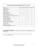
Page 26: ...ter the cooler the control box components will be resulting in longer component life Figure 16 Filter element removal Contact Wolfe Electric Inc a factory representative or a local service company to perform all other maintenance and repairs 5 10 CLEANING NOTICE If the oven is to be removed from its installed location for cleaning or servicing the following procedure is to be implemented 1 Shut of...

Page 27: ...h Pressure Generating fan filter Clean finger covers Clean bake chamber floor Clean bake chamber walls Clean bake chamber top Clean inside of face panel Clean control box sides and top Clean control box face and switches Clean conveyor Clean finger bodies Deep clean oven chamber Clean Main Fan Motor s Motor Cover s WARNING DANGER Oven must be cool and the electric cord unplugged before any cleanin...

Page 28: ...ty of toppings XLT ovens can be configured to cook a wide variety of food items This is accomplished by arranging the fingers to control the baking characteristics Generally speaking most cooking is a bottom up process The hot air from the bottom row of fingers has to go through the conveyor a distance of about 50 8mm heat the pan or screen and then actually cook raw dough The hot air from the top...

Page 29: ...erify the following items and then contact us before performing maintenance and repairs Electrical diagrams are located on page 32 34 and on the inside surface of the operator control panel lid 1 Oven is plugged in to the electrical receptacle 2 Circuit breakers in the building are on not tripped 3 Gas valve s are on 4 Gas hose quick disconnect is properly connected 5 Air is purged from the gas li...

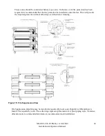
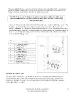
Page 30: ...pply and the electrical supply are to be provided by the customer prior to installation The picture above shows a typical utility rough in for a triple stack oven Preparing the utilities this way allows for an easy third deck addition if a double stack oven is initially installed All installations must conform to local building and mechanical codes Read and follow the Installation and Operation Ma...

Page 31: ...asy access and connection of gas and electric lines The electrical outlets Item 1 can also be located to the left of the gas line Figure 18 Gas Service view The picture above shows a close up detail of the gas service 3 4 gas hose assemblies with quick disconnects for each oven deck will be installed at each valve item 9 during the oven setup and installation Alternatively items 5 10 can be assemb...

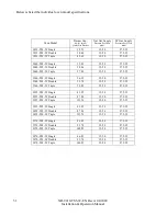
Page 32: ...5 20 27 5 35 2440 TS3 W Triple 57 09 15 20 27 5 35 3240 TS3 W Single 26 35 15 20 27 5 35 3240 TS3 W Double 52 70 15 20 27 5 35 3240 TS3 W Triple 79 05 15 20 27 5 35 3255 TS3 W Single 43 92 15 20 27 5 35 3255 TS3 W Double 87 84 15 20 27 5 35 3255 TS3 W Triple 131 76 15 20 27 5 35 3855 TS3 W Single 43 92 15 20 27 5 35 3855 TS3 W Double 87 84 15 20 27 5 35 3855 TS3 W Triple 131 76 15 20 27 5 35 3270 ...

Page 33: ...XD 9010 TS3 W EN Rev A 04 2009 Installation Operation Manual 32 8 ELECTRICAL DIAGRAMS 8 1 1832 TS3 W 2440 TS3 W 3240 TS3 W 3255 TS3 3855 TS3 W ...

Page 34: ...XD 9010 TS3 W EN Rev A 04 2009 Installation Operation Manual 33 8 2 3270 TS3 W 3870 TS3 W RIGHT HAND SIDE ...

Page 35: ...XD 9010 TS3 W EN Rev A 04 2009 Installation Operation Manual 34 8 3 3270 TS3 W 3870 TS3 W LEFT HAND SIDE ...

Page 36: ...XD 9010 TS3 W EN Rev A 04 2009 Installation Operation Manual 35 ...

Reviews: