6/17/2017
XKITZ XAMP-M2
10
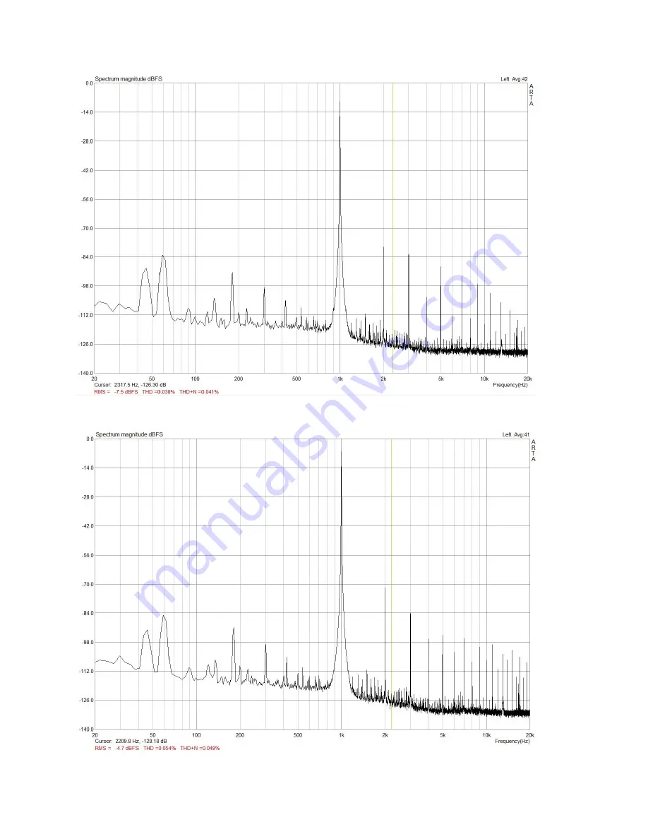
Figure 3.
Woofer, 2.83V into 8 Ohms (1W) THD=0.038% THD+N=0.041%
Figure 4.
Woofer Full Output, THD=0.054% THD+N=0.049%
Page 1: ...le with the new hi def audio players such as the Pono Specifications THD 0 044 THD N 0 046 Frequency Response Linear from 20Hz 80KHz CMRR balanced input 55dB Input Impedance 20K ohms unbalanced 40K balanced Input Overload 3 8V peak to peak Voltage Gain Adjustable Max 26dB Power Output Per Channel 12W RMS into 8 Ohms 21W RMS into 4 Ohms Filter Topology Linkwitz Riley Constant Voltage 4th Order 24dB...
Page 2: ...ed circuit board Many of the parts in this kit are temperature sensitive Overheating may damage them Always clean the soldering iron tip on the damp sponge prior to every solder joint Re tin whenever the tip gets a little dull tinning is the application of fresh solder to the tip of the iron until its shiny wipe excess on a damp sponge Inspect the solder joints They should be shiny and smoothly co...
Page 3: ... R1 R14 R15 R16 R19 R25 R27 R45 R50 R62 A RESISTOR 10K 1 BRN BLK BLK RED BRN 6 R4 R7 R10 R12 R49 R51 A 1 RESISTOR 20K 1 RED BLK BLK RED BRN 3 R2 R11 R17 A 1 RESISTOR 10K 1 BRN BLK BLK RED BRN 3 R21 R22 R23 A 2 RESISTOR 20K 1 RED BLK BLK RED BRN 2 R20 R24 A 2 RESISTOR 4 7 1 YEL VIO BLK SLV BRN 2 R3 R18 A RESISTOR 10 BRN BLK BLK 1 R26 A RESISTOR 15K 1 BRN GRN BLK RED BRN 1 R28 A RESISTOR 82 5K 1 GRY...
Page 4: ...the PCB silkscreen Be careful not to bend the leads on the op amp chips when inserting into the sockets 8 Install the 20 pin socket in the location on the board marked XO MODULE the row of resistors from R57 at the top through R56 at the bottom Install with the pin 1 notch toward R57 at the top of the MODULE Carefully insert the 20 pin component carrier into the 20 pin socket marked XO MODULE with...
Page 5: ...6 17 2017 XKITZ XAMP M2 5 Figure 1 PCB Parts Placement and Dimensions 0 12 3 4 0 12 3 0 Board Height 2 0 ...
Page 6: ...anced audio cable adds a second path to ground and this can cause audible 50 60Hz hum Balanced lines are more common in high end consumer and professional audio systems and are much less susceptible to noise Balanced lines allow you to run very long audio cables without allowing electro magnetic noise to couple into your signal They re also not susceptible to 50 60Hz hum there is no connection to ...
Page 7: ...oint between points where both the woofer and the tweeter are still solidly within their ideal operating frequency range Baffle Step Compensation The Baffle Step Compensation circuit or BSC if you choose to use it allows you to apply a low pass filter function to the audio signal to compensate for a phenomenon where sounds above a certain frequency determined by the size of the baffle or the front...
Page 8: ... AC and connect it to the Woofer speaker outputs Raise the Bass level pot until the output voltage is equal the Volts RMS listed in Table 4 below for your power supply voltage and woofer impedance The table also shows the max RMS watts per channel power you can expect for each setting 5 Now that you have your bass level set it s time to set the crossover Treble levels Connect your speakers to the ...
Page 9: ...er our Audio Grade 200W DC power supply the XAPS 200W It takes in AC from a power transformer and creates very clean well regulated DC voltage for your amplifier Troubleshooting If you re having trouble with your device check Table 5 below for possible cause and solution Table 5 Troubleshooting Guide Problem Possible Cause Solution Power supply not working no input signal Verify DC voltage input i...
Page 10: ...6 17 2017 XKITZ XAMP M2 10 Figure 3 Woofer 2 83V into 8 Ohms 1W THD 0 038 THD N 0 041 Figure 4 Woofer Full Output THD 0 054 THD N 0 049 ...
Page 11: ...6 17 2017 XKITZ XAMP M2 11 Figure 5 Tweeter 2 83V into 8 Ohms 1W THD 0 044 THD N 0 046 Figure 6 Tweeter Full Output THD 0 12 THD N 0 11 ...
Page 12: ...6 17 2017 XKITZ XAMP M2 12 Figure 7 XAMP M2 Schematic ...