


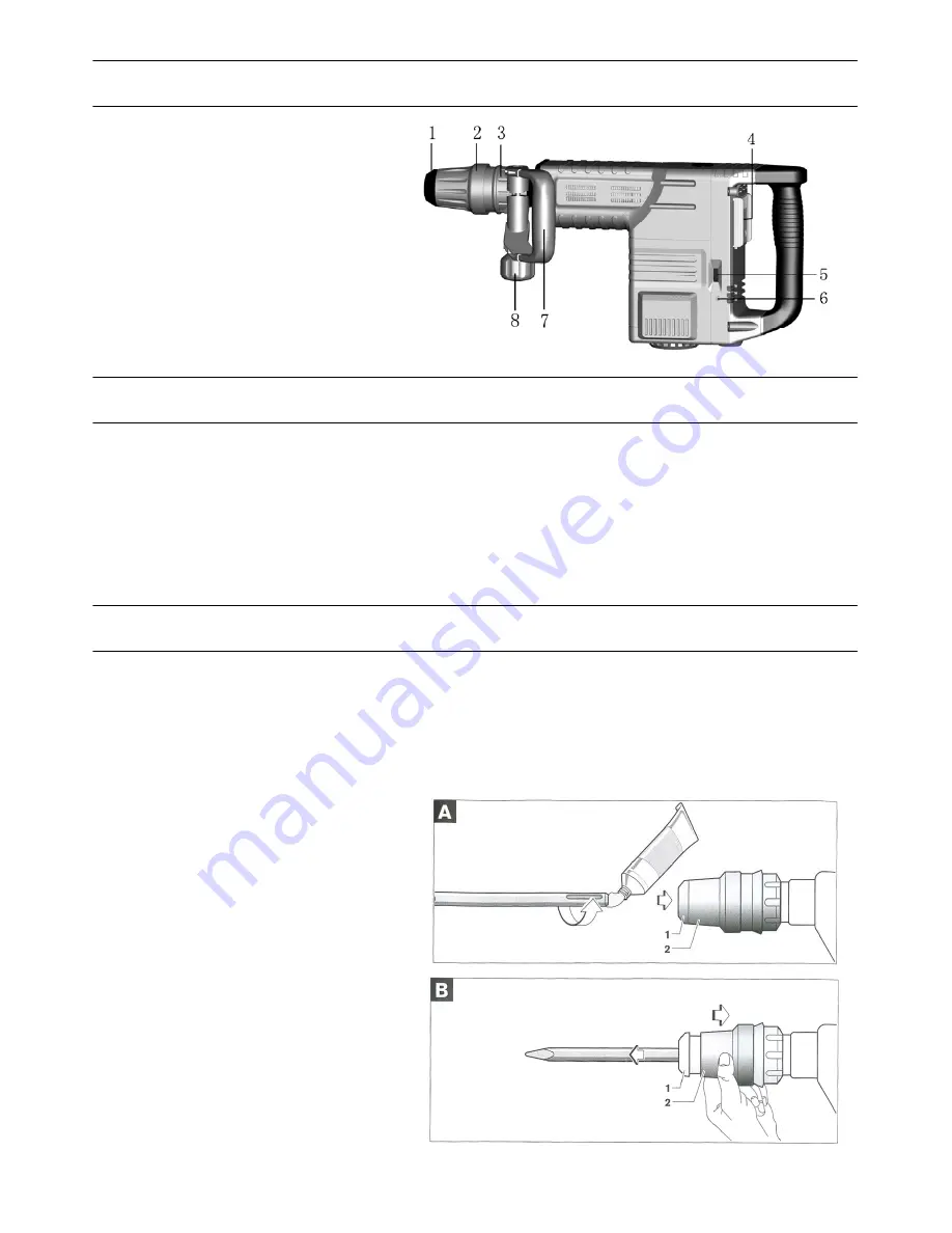
Name of the parts
1.
Hammer rod protector
2.
Protective lining
3.
Move limited ring
4.
Switch Push-And-Pull
5.
Speed Adjuster Function Knob
6.
Indicator
7.
Side Handle
8.
Function Knob
Assembly
Auxiliary Handle
Operate your power tool only with the
Side Handle
7.
The Side Handle
7
can be set to any position for a secure and low-fatigue working posture.
Loosen the Function Knob
8
, rotate the Side Handle
7
around the axis of the power tool to the required
position and tighten the Function Knob
8
again.
The Side Handle
7
can be mounted to a different position. For this, completely unscrew the Function Knob
8 and then pull out the hexagon bolt upward. Pull off the Side Handle
7
to the side and turn around the
remaining clamping element by 18
0
。
Mount the Side Handle
7
in reverse order.
Changing the tool
Before any work on the power tool itself, pull the mains plug.
With the SDS-max tool holder. Simpler and easier tool changing is possible without additional aids.
The Hammer rod protector 1 largely prevents the entry of drilling dust into the tool holder during
operation. When inserting the tool, take care that the Hammer rod protector 1 is not damaged.
A damaged
Hammer rod protector
should be changed immediately.
We recommend having this carried
out by an after-sales service.
Inserting (see figure A)
Clean and lightly grease the shank end
of the tool.
Insert the tool in a twisting manner into
the tool holder until it latches itself.
Check the latching by pilling the tool.
Removing (see figure B)
Push back the Protective lining
2
and remove
the tool.


