


ZCU102 Evaluation Board User Guide
50
UG1182 (v1.2) March 20, 2017
Chapter 3:
Board Component Descriptions
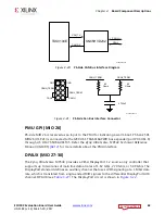
Ethernet PHY Reset
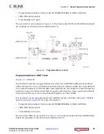
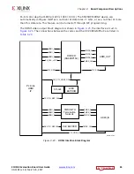
The DP83867IRPAP PHY U98 reset circuit is shown in
. The DP83867IRPAP can be
reset by the SW9 push-button (U59.6), the MAX16025 U22 MPSoC PS-side POR reset device
(U59.1), or the I2C0 connected U97 TCA6416A I/0 expander port P06 pin 10 (U59.3).
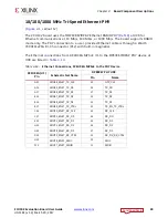
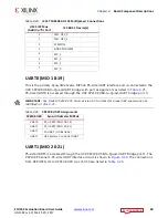
Ethernet PHY LED Interface
[
, callout 12]
The DP83867IRPAP PHY U98 LED interface (LED_0, LED_2) uses the two LEDs embedded in
the P12 RJ45 connector bezel. The LED functional description is show in
The LED functions can be re-purposed with a LEDCR1 register write available via the PHY's
management Data Interface, MDIO/MDC. LED_2 is assigned to ACT (activity indicator) and
X-Ref Target - Figure 3-13
Figure 3-13:
Ethernet PHY Reset Circuit
;
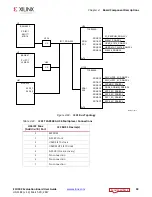
Table 3-15:
Ethernet PHY LED Functional Description
Pin
Type
Description
Name
No.
LED_2
61
S, I/O, PD
By default, this pin indicates receive or transmit activity.
Additional functionality is configurable by means of LEDCR1[11:8]
register bits.
Note:
This pin is a strap configuration pin for RGZ devices only.
LED_1
62
S, I/O, PD
By default, this pin indicates that 100BASE-T link is established.
Additional functionality is configurable by means of LEDCR1[7:4]
register bits.
LED_0
63
S, I/O, PD
By default, this pin indicates that link is established. Additional
functionality is configurable by means of LEDCR1[3:0] register
bits.


