


ZCU102 Evaluation Board User Guide
34
UG1182 (v1.2) March 20, 2017
Chapter 3:
Board Component Descriptions
USB0 (MIO 52-63)
The USB interface on the PS-side serves multiple roles as a host, device, and OTG controller.
The USB 3.0 interface is supported by the MPSoC GTR interface while the USB 2.0
capabilities of the SMSC USB3320C controller are shared on a common USB 3.0 micro USB
type AB connector (J96).
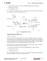
USB 3.0 Transceiver and USB 2.0 ULPI PHY
[
, callout 5]
The ZCU102 board uses a Standard Microsystems Corporation USB3320 USB 2.0 ULPI
Transceiver at U116 to support a USB connection to the host computer (see
). A
USB cable is supplied in the ZCU102 Evaluation Kit (standard-A connector to host computer,
micro-B connector to ZCU102 board connector J96). The USB3320 is a high-speed USB 2.0
PHY supporting the UTMI+ low pin interface (ULPI) interface standard. The ULPI standard
defines the interface between the USB controller IP and the PHY device which drives the
physical USB bus. Use of the ULPI standard reduces the interface pin count between the USB
controller IP and the PHY device.
The USB3320 is clocked by a 24 MHz crystal. Consult the Standard Microsystems
Corporation (SMSC) USB3320 data sheet for clocking mode details
The interface to the USB3320 PHY is implemented through the IP in the XCZU9EG MPSoC
Processor System (PS).
describes the jumper settings for the USB 2.0 circuit. Bold text identifies the
default shunt positions for USB 2.0 high speed on-the-go (OTG) mode.
X-Ref Target - Figure 3-3
Figure 3-3:
USB Interface
60
86%
86%
0,2
8/3,
86%
&RQQHFWRU
86%
*75
*757[5[
*75
0X[
86%
;


