


ZC706 Evaluation Board User Guide
27
UG954 (v1.5) September 10, 2015
Feature Descriptions
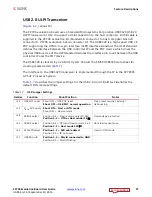
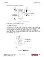
USB 2.0 ULPI Transceiver
[
, callout 19]
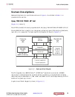
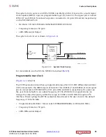
The ZC706 evaluation board uses a Standard Microsystems Corporation USB3320 USB 2.0
ULPI Transceiver at U12 to support a USB connection to the host computer. A USB cable is
supplied in the ZC706 evaluation kit (Standard-A connector to host computer, Micro-B
connector to ZC706 evaluation board connector J2). The USB3320 is a high-speed USB 2.0
PHY supporting the UTMI+ low pin interface (ULPI) interface standard. The ULPI standard
defines the interface between the USB controller IP and the PHY device which drives the
physical USB bus. Use of the ULPI standard reduces the interface pin count between the USB
controller IP and the PHY device.
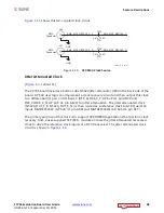
The USB3320 is clocked by a 24 MHz crystal. Consult the SMSC USB3320 data sheet for
clocking mode details
The interface to the USB3320 transceiver is implemented through the IP in the XC7Z045
AP SoC Processor System.
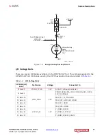
describes the jumper settings for the USB 2.0 circuit. Bold text identifies the
default OTG mode settings.
Table 1-7:
USB Jumper Settings
Header
Function
Shunt Position
Notes
J11
USB PHY reset
Shunt ON = USB PHY reset
Shunt OFF = USB PHY normal operation
Clean reset requires external
debouncing
J10
V
BUS
5V Supply
Shunt ON = Host or OTG mode
Shunt OFF = Device mode
J48
RVBUS select
Position 1–2 = Device mode only (10 K
Ω
)
Position 2–3 = OTG or Host mode (1 K
Ω
)
Overvoltage protection
J50
CVBUS select
Position 1-2 = OTG and Device mode 1
μ
F
Position 2-3 = Host mode 120
μ
F
V
BUS
load capacitance
J49
Cable ID select
Position 1-2 = A/B cable detect
Position 2-3 = ID not used
Used in OTG mode
J51
USB Micro-B
Position 1-2 = Shield connected to GND
Position 2-3 = Shield floating


