


10
ML40x Getting Started Tutorial
UG083 (v5.0) June 30, 2006
Board Setup
R
Board Setup
1.
Position the ML40
x
board so the Virtex™-4 and Xilinx logos are oriented near the top
edge of the board.
2.
Make sure the power switch, located in the upper right corner of the board, is in the
OFF position.
3.
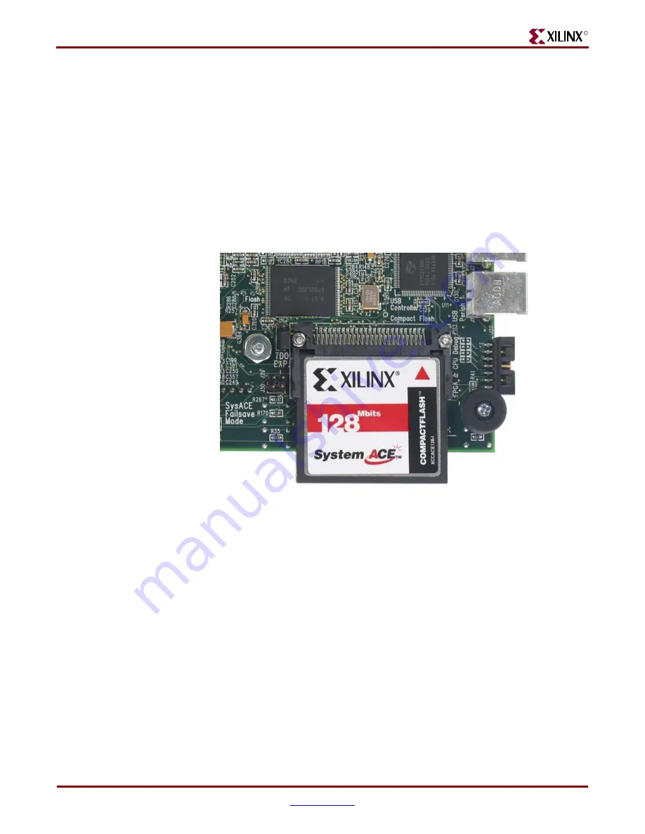
Locate the CF card slot (on the back side of the ML40
x
board), and carefully insert the
System ACE™ CF card with its front label facing away from the board.
shows
the back side of the board with the CF card properly inserted.
Note:
The CF card provided with your board might differ.
Caution!
Be careful when inserting or removing the CF card from the slot. Do
not
force it.
Note:
The ML405 board is similar but not identical to the example shown in
4.
Connect the AC power cord to the power supply brick. Plug the power supply adapter
cable into the ML40
x
board. Plug in the power supply to AC power.
5.
Set the following switches:
♦
Configuration address and mode DIP switch (6-position DIP switch) to
000111
♦
Configuration source selector switch (3-position slide switch) to SYS ACE
Figure 1:
ML40
x
Evaluation Platform with CF Card
UG083_01_111004


