background image


3-3 

Step 2 : 

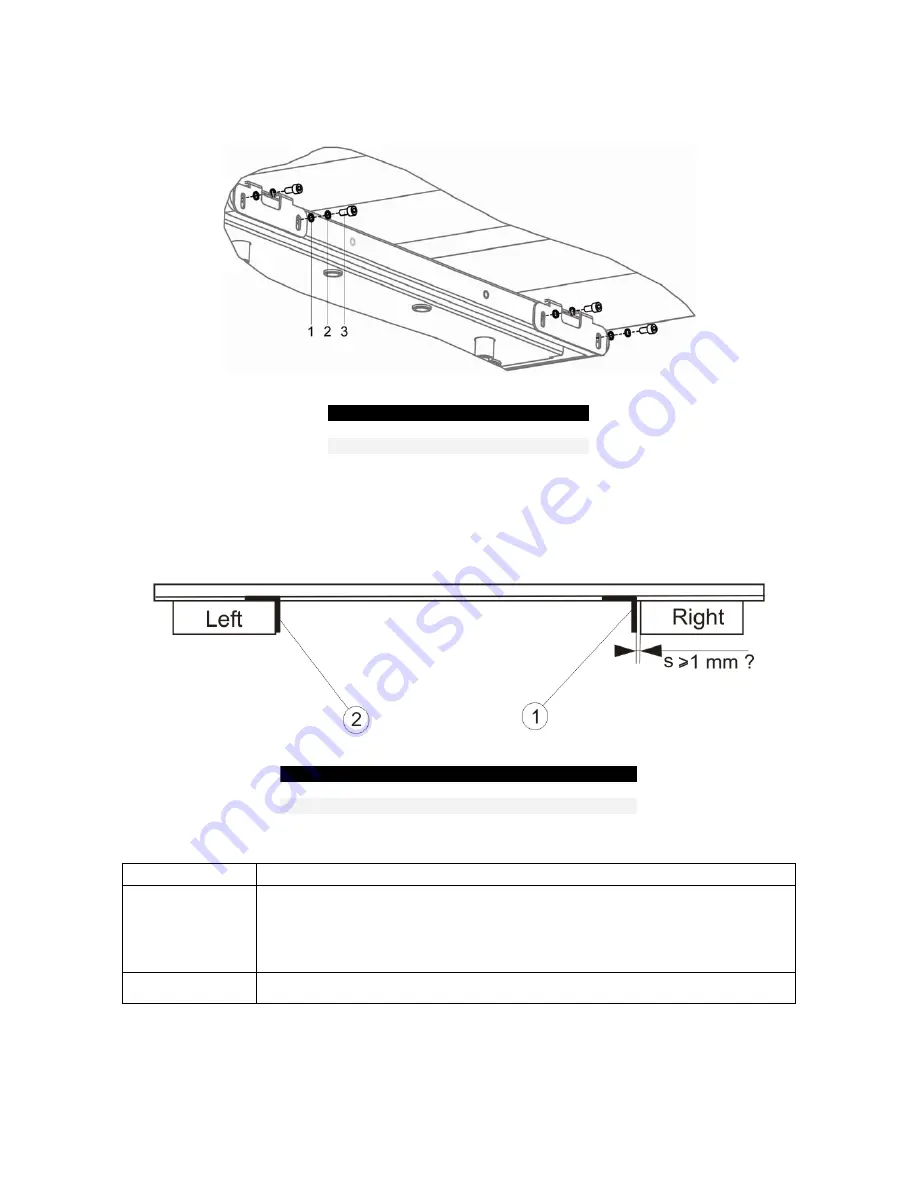
Mount the left side of the bars with the mounting supports to the printer’s stand as indicated on 
the image below. 


No. 

Description 

1 Plain 

washer 

M6 

Tooth lock washer M6 

Hexagon bolt M6x12 


Step 3 : 

Check the gap (s) between the adjustable mounting support (1) on the right hand side and the 
printer stand and perform the correct action. This has to be done for both roll unit bars. See 
below. 


No 

Description 

1 Adjustable 

mounting 

support 

Left mounting support 

Gap between support and printer foot 


IF … 

THEN … 

s = 1 or s > 1 mm 

  loosen the 4 screws holding the support on the roll unit bar, 

  slide the support against the right side of the printer’s stand,  

  mount the support to the printer’s stand and fix the 4 screws holding the support 

on the roll unit bar. 

s < 1mm 

  mount the support to the printer’s stand without adjusting. 


Summary of Contents for 82xx

Page 1: ...August 2007 701P47496 Xerox 82xx 83xx Wide Format Printer Unwinder Winder User Guide ...

Page 2: ... granted including without limitation material generated from the software programs which are displayed on the screen such as icons screen displays looks etc Printed in the United States of America XEROX and all Xerox product names mentioned in this publication are trademarks of XEROX CORPORATION Other company trademarks are also acknowledged PANTONE is a registered trademark of Pantone Inc Change...

Page 3: ...ire Rockhopper 3 and Viper 3 64H4 23H3 2 2 2 On a ValueJet 1604 3 65H5 24H3 2 3 Installing the tensioning bars 3 66H6 25H3 2 4 Mounting the PCB Box 3 67H8 26H3 2 5 Connecting the cables 3 68H9 27H3 3 Calibrating the UW W 100 3 69H10 28H3 3 1 Calibrating the rear tensioning system 3 70H10 29H3 3 1 1 Checking the calibration 3 71H10 30H3 3 1 2 Adjusting the tensioning systems 3 72H14 31H3 3 2 Calibr...

Page 4: ...ii This page is intentionally left blank ...

Page 5: ... SAFETY INSTRUCTIONS General safety instructions that must be observed to use the equipment safely are explained below Do not stand on or place heavy objects on the unit Doing so may result in the unit tipping or falling over and causing injury Do not attempt to plug in electrical plugs with wet hands Doing so may result in electrical shock Do not use thinner benzene alcohol or other active agents...

Page 6: ...n be recognized If text or illustrations are invisible clean the label When cleaning labels use a cloth with water or neutral detergent Do not use a solvent or gasoline If an operation label has been damaged lost or cannot be recognized replace the label Foot switch label Roll unit handle label Front tensioning label Rear tensioning label PCB box label ...

Page 7: ...n symbol is attached to a product it means the product is covered by the European Directive 2002 96 EC Please inform yourself about the local separate collection system for electrical and electronic products Please act according to your local rules and do not dispose of your old products with your normal household waste The correct disposal of your old product will help prevent potential negative ...

Page 8: ...1 4 This page is intentionally left blank ...

Page 9: ...he roll media 5 Roll unit bar Supports the roll units 6 Roll unit Supports the roll media 2 1 2 Rear Unwinder No Name Function 1 Rear tensioning system Adjust the tension between the print platform and the unwinding system 2 Roll unit Supports the roll media 3 Motorized roll unit Supports and unwinds the roll media 4 Roll unit bar Supports the roll units On the picture above the winding system is ...

Page 10: ...uttons Motor turns LED flashes Motor is off LED is out Motor accelerates LED burns continuously Outside printing Inside printing 4 Backwards button Roll off unwinder Roll up unwinder 5 Forwards button Roll up unwinder Roll off unwinder 6 Winder 100 switch Toggle between Manual 0 and Automatic I mode Manual 7 Winder 100 LED Automatic LED lights up when pushing one of the buttons Motor turns LED fla...

Page 11: ...old the parts in their position and to protect them 2 2 1 For Rockhopper 3 Spitfire and Viper 2 2 1 1 Packaging box No Part Description Quantity 1 Box 1 Bracket arms 1 2 Left bracket 1 3 Keyboard bracket 1 4 Box 2 PCB box 1 5 Box 3 Winder kit 1 6 Roll unit bar 2 7 Rear tensioning bar 1 8 Front tensioning bar 1 Please refer to the next page for the contents of this box ...

Page 12: ...gon key 5 mm 1 6 Hexagon key 6 mm 1 7 Philips screwdriver p2 1 8 Spacer 10 9 Foot switch 1 10 Motor twist cable 1 11 Adjustment plate 1 12 D lock shafts 2 13 Keyboard cable 1 14 Screw set 1 15 Screw M4x10 4 16 Screw M3x5 4 17 Screw M5x8 2 18 Screw M6x16 16 19 Washer M5 4 20 Spring washer M6 16 21 Washer M6 16 22 Lock washer M6 1 23 User s Guide 1 ...

Page 13: ...x No Part Description Quantity 1 Box 1 Bracket arms 1 2 Left bracket 1 3 Keyboard bracket 1 4 Box 2 PCB box 1 5 Box 3 Winder kit 1 6 Roll unit bar 2 7 Rear tensioning bar 1 8 Front tensioning bar 1 Please refer to the next page for the contents of this box ...

Page 14: ...6 mm 1 7 Philips screwdriver p2 1 8 Spacer 10 9 Foot switch 1 10 Motor twist cable 1 11 Adjustment plate 1 12 Lock shafts 2 13 Keyboard cable 1 14 Power cable EU UK 2 15 Screw set 1 16 Screw M4x10 4 17 Screw M3x5 4 18 Screw M5x8 2 19 Screw M6x16 8 20 Self locking screws M6x16 8 21 Synthetic Washer M5 4 22 Spring washer M6 8 23 Washer M6 8 24 Lock washer M6 1 25 User s Guide 1 ...

Page 15: ...NIT 3 1 GENERAL SEQUENCE UNPACK ALL ITEMS MOUNT THE ROLL UNIT BARS MOUNT THE BRACKETS FOR THE TENSIONING BARS INSTALL THE TENSIONING BARS CALIBRATE THE UNWINDER WINDER 100 ADJUST THE WEIGHT SUPPORTS UNDER THE ROLL UNIT BARS ...

Page 16: ...ls needed No Description Quantity needed RH3 SPFR ValueJet 1 Roll unit bar 2 2 2 Hexagon bolt M6x16 8 8 3 Plain washer M6 8 8 4 Tooth lock washer M6 8 8 5 Hexagon wrench 5 mm 1 1 Procedure Step 1 Position the roll unit bars 1 on the printer stand as shown on the image below ...

Page 17: ...nd and perform the correct action This has to be done for both roll unit bars See below No Description 1 Adjustable mounting support 2 Left mounting support 3 Gap between support and printer foot IF THEN s 1 or s 1 mm loosen the 4 screws holding the support on the roll unit bar slide the support against the right side of the printer s stand mount the support to the printer s stand and fix the 4 sc...

Page 18: ...acket to the bottom of the X rail Note that the positioning of the left and right bracket is different depending on the size of the machine No Description 1 Left bracket arm 2 Unused holes 3 Left leg of the printer stand 4 Right leg of the printer stand 5 Right bracket arm Step 2 Fix the screws of the right bracket On the Left Bracket install 4 screws on the right side and 2 screws on the left sid...

Page 19: ...tions Notes Before installing the winding system on a ValueJet it is recommended to loosen screws fixing the printer from its stand and push it to the rear and tighten the bolts again This to be sure that the machine is well positioned Step 1 Screw the self locking bolts half way in Step 2 Hook the left and right bracket over the four screws and pull Step 3 Tighten the bolts of the right bracket ...

Page 20: ...p 1 Insert the two shafts 1 in the left adjustable bracket at the front and rear front rear Caution Use care when lifting the tensioning bars to avoid bending the bars Step 2 Position the front tensioning bar 1 between the D lock shafts of the left and right bracket in such a way that it fits the corresponding D hole in the plates 2 of the tensioning bars Notes While installing the tensioning bar ...

Page 21: ...ensioning bar at both sides with 2 pan head screws These screws have to be fixed before installing the front tensioning system Caution Be sure to calibrate the complete system before using it Please refer to the next chapter for this issue Notes Install the remaining screws on the left bracket Tighten all screws ...

Page 22: ...ntity 1 PCB Box 1 2 Screw M5x8 2 3 Washer M5 4 4 Hexagon wrench 3 mm 1 Procedure Step 1 Mount the two screws with each two spacers to the stand Step 2 Place the PCB Box 2 against the stand and slide it with the holes over the screws 1 and push it downwards until it is fixed ...

Page 23: ... 100 packaging box Step 1 Connect the power cable to the power supply connector Step 2 Check if the all cables of the UW W are connected to the correct connector 1 to 6 See image below for the location of the connectors Nr Description 1 Power supply connector 2 Front motorized unit connector 3 Rear motorized unit connector 4 Foot switch connector 5 Not used 6 Operation panel connector Notes With a...

Page 24: ...The procedure below describes the calibration check of the rear tensioning system The method to check the front tensioning system is the same However the front and rear tensioning bars use different bars to complete the calibration Procedure PART 1 PREPARING THE SYNTHETIC PAPER STRIP Step 1 Put the pressure rollers in the up position Step 2 Go to the back of the machine Step 3 Create a loop with t...

Page 25: ...essure rollers No Description 1 Synthetic paper strip 2 Paper loop 3 Tensioning bars 4 Pressure rollers Step 6 Go to the FRONT SIDE of the printer Step 7 Carefully pull the strip to create some tension Caution Don t pull too hard on the strip This will loosen the tape resulting in the fact that the loop becomes longer leading to a bad calibration check Make sure that you have an equal tension on t...

Page 26: ...stment plate onto the strip and slide it against the pressure rollers Step 2 Draw a line on the strip Step 3 Slide the strip 1 to position 2 as indicated on the image below No Description 1 Synthetic paper strip 2 Paper loop 3 Tensioning bars 4 Pressure rollers ...

Page 27: ...check Make sure that you have an equal tension on the left and right of the strip Step 5 Place the adjustment plate onto the strip and slide it against the pressure rollers See image below Step 6 Draw a line for the second time The following two situations can be obtained Line overlap each other well adjusted Line does NOT overlap each other perform the adjustment procedure as described in the nex...

Page 28: ...ont tensioning system is the same Procedure Step 1 Standing at the REAR SIDE of the unit remove the cover 1 of the adjustable bracket 3 Tool Hexagon wrench 2 5 mm No Description 1 Cover 2 Screws 3 Adjustable bracket Step 2 Loosen don t remove the 4 screws on the side of the adjustable bracket Tool Hexagon wrench 4 mm No Description 1 Screws 2 Adjustable bracket ...

Page 29: ...in Position 2 Tool Hexagon wrench 3 mm REAR REAR 1 Adjustment screws IF Line 2 lays THEN turn the adjustment screws as follows BEFORE line 1 Case A on image above BEHIND line 1 Case B on image above Caution Make sure to turn both adjustment screws an equal amount of turns Step 4 Check the calibration again and repeat the adjustment until the lines overlap each other ...

Page 30: ...he FRONT roll unit The procedure to check the rear roll unit is the same In the procedure line 1 is drawn at the RIGHT side of the printer line 2 at its LEFT side Procedure PART 1 PREPARING THE SYNTHETIC PAPER STRIP Step 1 Put the pressure rollers in the up position Step 2 Install an empty core between the roll unit and the motorized roll unit at the front side of the printer Step 3 Standing in fr...

Page 31: ...paper strip 1 is a little tensioned No Description 1 Synthetic paper strip 2 Loop 3 Core 4 Pressure rollers Caution Don t pull too hard on the strip This will loosen the tape resulting in the fact that the loop becomes longer leading to a bad calibration check Make sure that you have an equal tension on the left and right of the strip ...

Page 32: ... the adjustment plate onto the strip and position it against the pressure rollers as indicated on the image below Step 2 Draw a line See image below Step 3 Slide the strip 1 to position 2 as indicated on the image below No Description 1 Synthetic paper strip 2 Loop 3 Core 4 Pressure rollers ...

Page 33: ... loosen the tape resulting in the fact that the loop becomes longer leading to a bad calibration check Make sure that you have an equal tension on the left and right of the strip Step 6 Draw a line for the second time The following two situations can be obtained Line overlap each other well adjusted Line does NOT overlap each other perform the adjustment procedure as described in the next chapter ...

Page 34: ...ow Adjusting the FRONT Units IF line 2 lays THEN BEFORE line 1 Remove spacers on the left front unit or add spacers on the right front unit BEHIND line 1 Add spacers on the left front unit or remove spacers on the right front unit Adjusting the REAR Units IF line 2 lays THEN BEFORE line 1 Add spacers on the left rear unit or remove spacers on the right rear unit BEHIND line 1 Remove spacers on the...

Page 35: ...ious step BETWEEN the roll unit bar 3 and the printer s stand 2 See images below No Description 1 Spacer 2 Printer s stand 3 Roll unit bar Step 4 Check the calibration of the roll system again and do an adjustment again if necessary Step 5 Now fix the screws of the roll unit bar so the bar doesn t move anymore ...

Page 36: ...n a 65 printer There are 2 weight supports on the UW W 100 system for a 65 machine see the images below for their positions FRONT VIEW No Description 1 Weight support 3 3 3 2 Location of the weight supports on a 90 printer There are 4 weight supports on the UW W 100 system for a 90 machine see the images below for their positions FRONT VIEW No Description 1 Weight support ...

Page 37: ...e weight supports with force when they reach the floor Instructions Lower the weight supports of the UW W 100 till they reach the floor A hexagon wrench 6 mm can be used as indicated below No Description 1 Hexagon wrench 6 mm 2 Turning direction to lower the support ...

Page 38: ...3 24 This page is intentionally left blank ...

Page 39: ...E POWER ON OFF The switch in located on the power supply box Its status is marked with O and I I Switched ON Power LED on control panel of winding system will light up O Switched OFF Power LED on control panel of winding system will not be lid ...

Page 40: ...r Spitfire 65 Rockhopper 3 65 and Viper 65 For Spitfire 90 Rockhopper 3 90 and Viper 90 1625 mm 1653 mm 2280 mm 63 98 in 65 07 in 89 76 in Minimum media width For ValueJet 1604 For Spitfire 65 Rockhopper 3 65 and Viper 65 For Spitfire 90 Rockhopper 3 90 and Viper 90 1000 mm 210 mm 210 mm 39 37 in 8 27 in 8 27 in Inner core diameter 50 8 mm or 76 2 mm 2 in or 3 in Step 6 Remove the packaging of the...

Page 41: ...Step 10 Install an empty core between the front roll units a Make sure the core is longer than the media width b Load it centrally as described in previous step Step 11 Use the foot switch to release some media at the rear Step 12 Load media through the rear tensioning bar over the print platform under the pressure rollers as pictured below 1 Roll unit 2 Media roll 3 Rear tensioning bar 4 Print pl...

Page 42: ...talled between the front roll units Make sure to have an equal tension on both sides of the media HINT To ease the winding up of the media on the front core it is permitted to cut the media in a V shape Step 17 Tighten the media straight to the core with tape Step 18 After closing the front cover the media initialize will start Step 19 Set the winder FRONT unit to ACTIVE The front tensioning syste...

Page 43: ......

Page 44: ......

Reviews: