


Copyright © 2015 Ruckus Wireless, Inc.
Published May 2015
(OPTIONAL) MOUNTING INSTRUCTIONS
Xo-1 ANTENNA COVERAGE
The Xo-1 AP includes internal omni 5GHz and 2.4GHz
antennas, and has two female N-type connector for optional
customer-ordered external 5GHz antennas.
Internal Omni Antennas
When the internal antennas are used, the Xo-1 is best
deployed where lateral beamforming can provide the greatest
reach and throughput to a wide coverage area, or to provide
the greatest distance between APs in a connecting mesh
device. See Figure 1 for a typical side view coverage pattern,
see Figure 2 for a typical top view coverage pattern, and see
Figure 3 for a typical mesh coverage pattern.
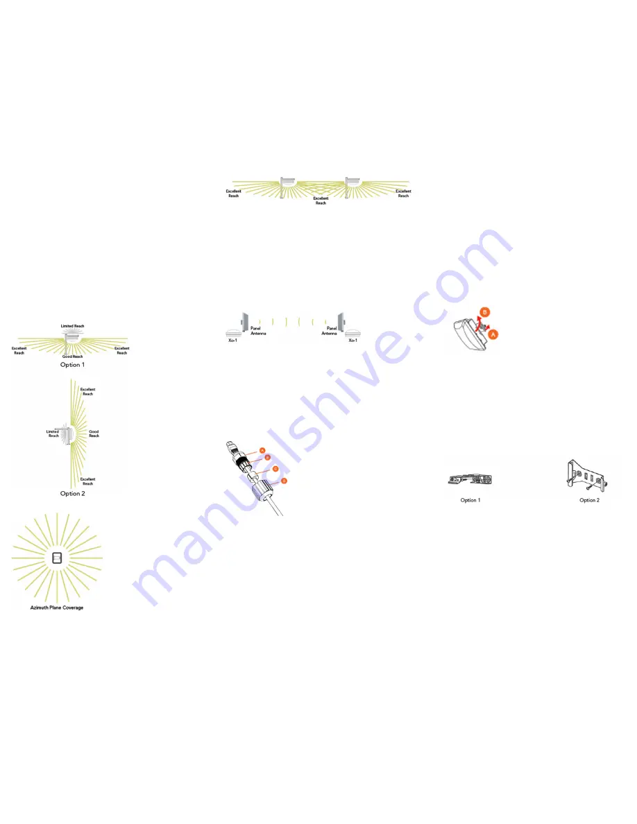
Figure 1 – Typical AP internal omni coverage, side view
Figure 2 – Typical AP internal omni coverage, top view
Figure 3 – Typical AP internal-antenna mesh elevation plane
coverage, side view
External Customer-Supplied 5GHz Antennas
Instead of the internal omni 5GHz antennas, the Xo-1 can use
one or two external 5GHz antennas in point-to-point and other
specialized deployments for extended backhaul, higher
throughput, and/or larger or smaller beamwidths than those
provided by Ruckus Wireless AP internal antennas.
Figure 4 shows the Xo-1 used in a typical backhaul
deployment.
Figure 4 – Typical AP long-range point-to-point deployment
Step 1: Connecting and Sealing the RJ-45 Cable
The AP uses one RJ-45 cable for Ethernet backhaul and
Power over Ethernet (PoE). Connect and seal the cable using
the M25 data cable gland.
Feed the end of the RJ-45 cable through the sealing nut (D in
Figure 5), rubber sealing insert (C in Figure 5), clamping ring
assembly (B in Figure 5) and cable gland base (A in Figure 5).
Figure 5 – RJ-45 cable and cable gland assembly
Use a wide flat-blade screwdriver to remove the blanking cap
from the AP.
Connect the cable to the Ethernet port in the AP.
Tighten the cable gland base into the AP chassis to 7 N.m or
62 in-lbs.
Wrap the clamping ring assembly around the rubber sealing
insert. Make sure that the clamping ring assembly fully
encloses the rubber sealing insert.
Seat the clamping ring assembly and rubber sealing insert in
the cable gland base.
Tighten the sealing nut to 1.1 N.m or 10 in-lbs, or until the
rubber sealing insert is compressed.
Continue with Step 2a: Attaching the Mounting Bracket to a
Flat Surface or Step 2b: Attaching the Mounting Bracket to a
Metal Pole.
Step 2a: Attaching the Mounting Bracket to a Flat
Surface
The AP mounting bracket attaches to the AP using a captive
screw. Use a medium flat-blade or No. 2 Phillips screwdriver to
loosen the captive screw (A in Figure 6) and pull up on the end
of the bracket to remove the bracket from the AP (B in Figure
6).
Figure 6 – Removing the mounting bracket
Using either of the two options shown in Figure 7, hold the
mounting bracket at the location on the mounting surface
where you want to mount the AP. Use the holes on the
mounting bracket as a template to mark the locations of the
mounting holes.
NOTE:
The mounting bracket can be mounted to a vertical or
horizontal surface to support the AP in the required orientation.
Figure 7 – Mounting bracket on a flat surface
Remove the mounting bracket from the mounting surface.
Drill holes required for the customer-supplied mounting
hardware.
Attach the mounting bracket to the flat surface using the
mounting hardware.
Using the mounting hardware instructions, tighten the hardware
to secure the mounting bracket.
Continue with Step 3: Mounting the AP.


